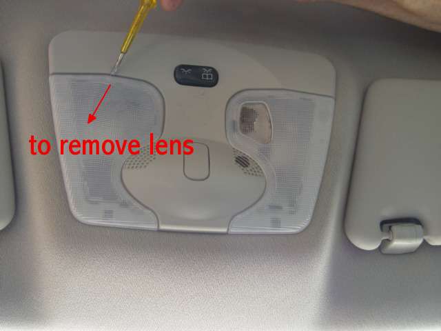
The off position is therefore reached when the toggle switch is flat, tipped neither left nor right. The interior lamp unit has two separate lenses, behind each is a festoon bulb, for general interior light front and rear, the other is more a spot light, it is lens being built into the right hand lens cover, more suited to reading maps etc.
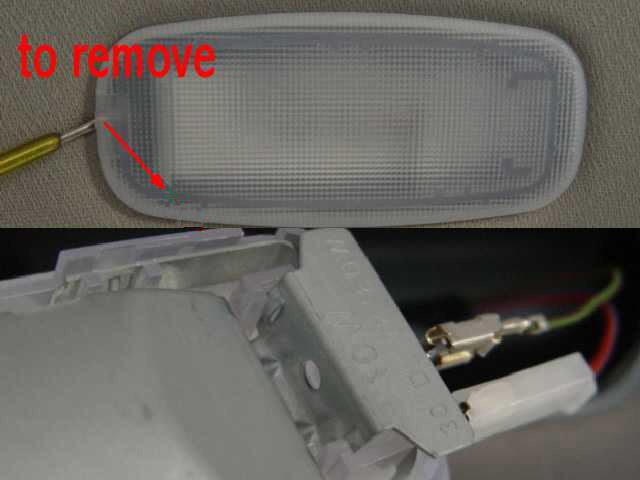
The lamp lens/covers are best removed with a small screw driver which can be used to ease the lens down and away from the roof lining, take care it is brittle plastic.
The two festoon bulbs/lamps are easily replaced they merely have to be removed from their spring clips, the spot light bulb however is a different story as the lamp housing has to be lowered to get to the bulb. We will look at that later,
when putting the O/S lens back, engage all the clips in their respective slots the N/S lens has not got slots, gently ease the cover back into the fully housed position.
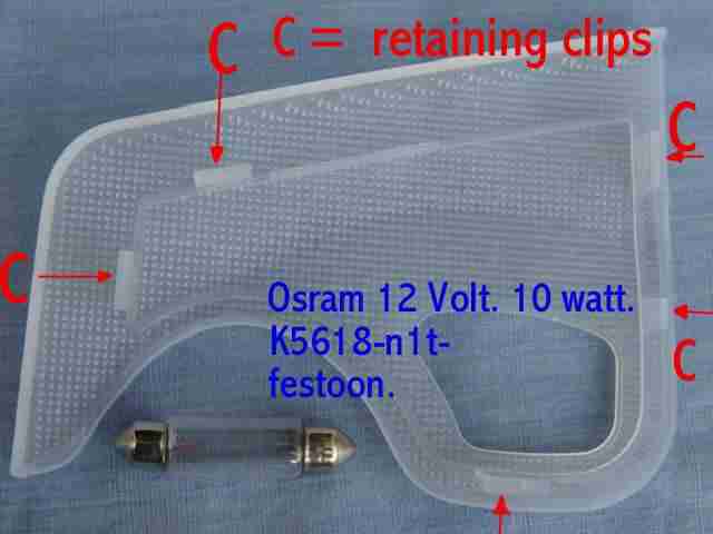
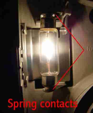
When replacing the festoon type bulbs make sure the spring clips into which they locates are holding the bulb firmly, if not slightly bend the sprung contact, note that one of the clips is fixed , do not attempt to bend this one or the unit will be damaged. this will have the effect of tightening the bulb and stop intermittent operation which can occur when driving with the lights on.
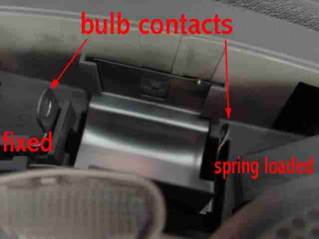
This is one of the front light fittings, however in the case of the rear lighting unit both contacts are spring loaded.
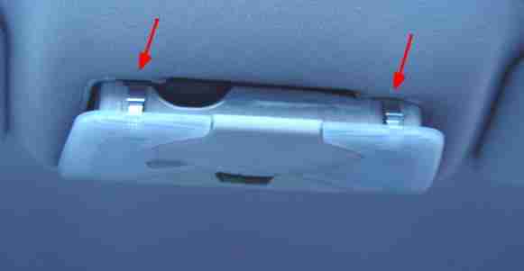
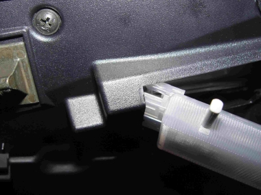
 Should it become necessary to install a new bulb in the spot light the complete lamp housing will need to be lowered, the handbook shows a special tool being used! This is not required on my 160/2002 Elegance, what you need are two small screw drivers to release the two metal spring clips situated at the front of the lens , marked by arrows in the photo. Once these are eased the housing can be lowered. Note the location of the air vent to the air conditioning sensor.
 To replace the unit this can be done with the lenses in place relocate the rear fixed lugs push up evenly from the front and you will hear the front clips engage. Remember to test you lamp after replacing.
Note, In some instances it may be found that the housing is also held by a 'Phillips' screw to the roof and this must also be unscrewed before trying to release the 2 spring clips.
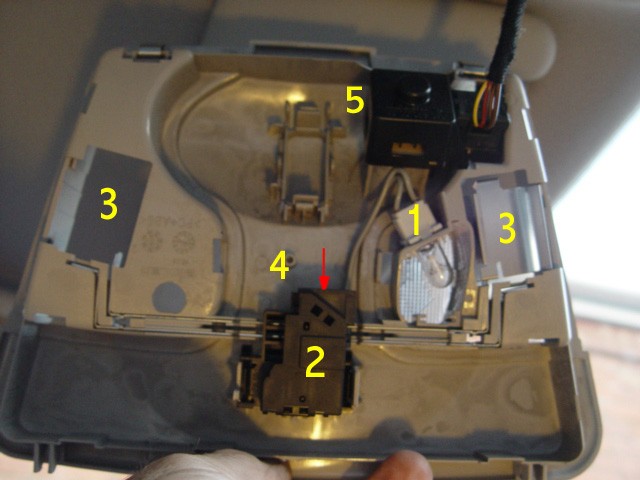
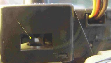 Situated behind the air sensor port is a very small electric rotary pump which is vacuuming air from the car all the time the ignition is on, it is this sensor that maintains a constant temperature in the car. The motor although very quiet can be heard running when the engine is off with the ignition on. the yellow arrow is pointing to the stationary impellor.
The air conditioning fan/sensor unit is a tight push fit and to get at the bearing requires removal of the clip on the top cover. A good blow out of the housing is a good idea whilst applying a drop of oil.
 Search in the location indicated in the handbook and you will find nothing, apart from not having the tool provided in the wallet as indicated,
now we know why! Its not required the fitting has been changed but nobody thought to tell Mercedes-Benz.( see page 136 )have spoken with one of the mechanics at my branch of MB it appears it never was removed as the handbook indicates!
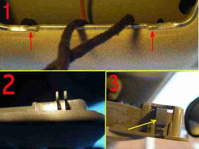
If you take a look at the various fittings removal becomes easier, In 1 You can see the two projections that locate on the clips and thereby retain the lamp housing. 2 The fixed clips at the rear of the housing which fit onto the rim in the roof lining. 3 One of the clips from the front which have to be released to allow the housing to be removed.
 Once lowered the bulb can be replaced, A push fit O/S 12volt W5W (E1)2GL W1B The electrical contacts can also be checked, being connected by an removable contact block. In addition the interior temperature sensor for the air conditioning is located within that housing, Thank you Darren, Mercedes-Benz Chichester.
1
Spot light bulb & holder.
2
Lighting switch.
3
Festoon lamp carriers.
4
Contact block housing for lighting.
5
Ultra small air pump. See enlarged photos of fittings above.
Once lowered the bulb can be replaced, A push fit O/S 12volt W5W (E1)2GL W1B The electrical contacts can also be checked, being connected by an removable contact block. In addition the interior temperature sensor for the air conditioning is located within that housing, Thank you Darren, Mercedes-Benz Chichester.
1
Spot light bulb & holder.
2
Lighting switch.
3
Festoon lamp carriers.
4
Contact block housing for lighting.
5
Ultra small air pump. See enlarged photos of fittings above. 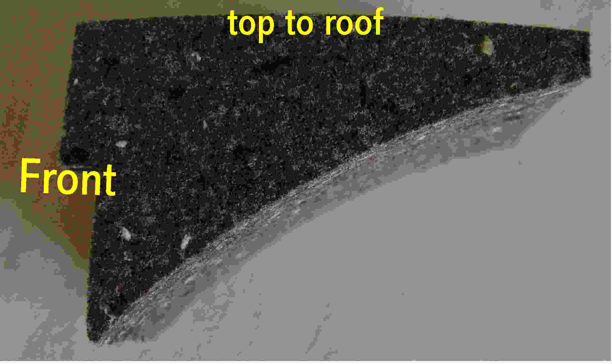
Before re-fitting the lamp housing make sure that the high density foam block is in position between the roof and the lining, if for any reason it has become dislodged or missing more noise than is normal may be heard coming from the rotary air pump, when the ignition is on. When positioned correctly it sits central and to the rear of the lamp housing, so that when you operate the switch no movement is felt. i.e. the housing is not pressed towards the roof of the car. Note this block is not fixed in position.
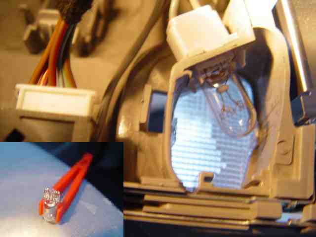 Removing the bulb is difficult and replacing with my size fingers is worse, so I used my fuse carrier to replace the bulb
While dealing with interior lighting we shouldn't forget the light in the rear, easily maintained, easily removed, place a small screwdriver into the slot indicated by the arrow, which may be at either end dependent on how it was last fitted, gently push against the retaining clip and the complete light/lens assembly will comes away with the cable. I found it easier to then remove the lighting unit from the cable,
there are two connections one live one earth, for safety simply replace them as found.
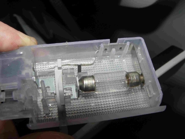
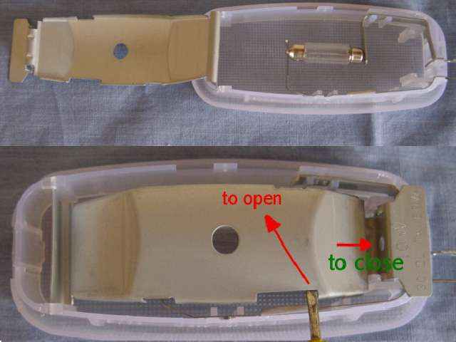 The lens assembly can be laid face down and and the metal cover eased open with a small screw driver. I found the best position was where the screwdriver is sited in the photo. The festoon bulb housing is then exposed along with the two sprung contacts. All of these plastic parts are quite brittle so take care. The bulb is the same size and type and those used in the front and can be replaced very easily, the metal cover can then be re-located and is slightly moved towards the end of the housing (see arrow) which enables it to relocate, the serviced unit can be then replaced in the car. ensure the cable is tucked away as you replace the unit into the recess, place the end without the clip in first and then push the lens unit into place ensuring it clips in firmly. There is no independent operating switch for this light, it operates on all of the courtesy lights switches including the boot, as well as from the front general lighting position only.
It does not work in conjunction with the spot light position.
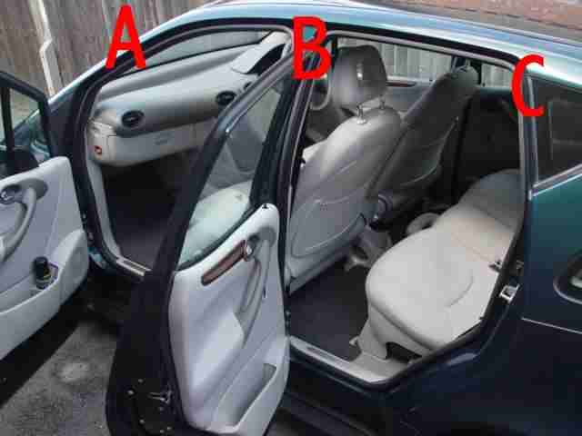
Before moving outside the car lets identify the parts we are going to refer to, the upright of the car structure in the emergency services at least are given letters of identification starting from the front 'A' and so on. In the case of the 'A' Class the front door closes and the rear door is hung on the 'B' Post, we can also use them to identify parts on the vehicle and where they are located. back.
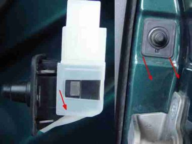
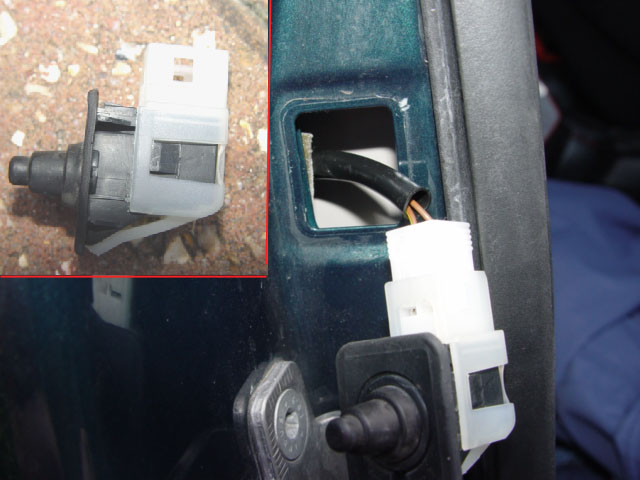
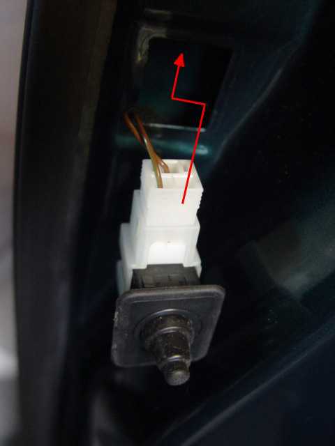 Courtesy door switches are located on the 'B' and 'C' Posts, near the door catches. as well as one on the boot lid. All appear to be of the same plunger type, connected by a twin wire connection. Previous cars I have owned have been single wire, the earth being made by the switch on the body work, crude but effective. The switch is best removed by placing a thin screwdriver blade to the base of the switch and easing away from the post. Having released the location catch at the bottom the switch can then withdrawn from its respective location. If it is necessary to replace a switch then the thin plastic sides have to be eased away from the switch to release it from the connector, I have not attempted this but caution should be taken not to damage the connector, the new switch should just clip back into place.
Having replaced the switch, place it back into the appropriate post and ensuring the top is flush with the post, gently push the bottom in until the plastic spring clip re-locates.
 1
The switch on the boot is a double action switch which automatically turns the interior light on when the boot is opened,
2
However if the boot lid is going to open for a prolonged period the interior light can be turned off by pulling on the plunger peg of the boot switch, it will be felt to extend about another 1/2 an inch from the boot lid, after the normal time-lapse the interior light will go off.
1
The switch on the boot is a double action switch which automatically turns the interior light on when the boot is opened,
2
However if the boot lid is going to open for a prolonged period the interior light can be turned off by pulling on the plunger peg of the boot switch, it will be felt to extend about another 1/2 an inch from the boot lid, after the normal time-lapse the interior light will go off.When you close the boot the switch will revert to its normal working. This switch does not appear to be so robust as those on the doors, the protruding plunger can be easily damaged or broken when cleaning around the edge of the boot lid, which is what happened in my case. As a result the light would not go off when the boot was closed. To overcome this problem a stuck a rubber cap over the peg thereby increasing its length which cured the problem without the cost of a new switch. If you have the same problem remember before you glue anything on the plunger that it has got to enter the boot lid when its closed, so leave room for movement, or you will smash to switch completely as you close the lid
Lighting Problems
If you have problems with the interior light NOT going off when driving, check all doors this will cause the light to remain on even when the vehicle is parked.
If the car is locked with a ( not fully closed ) or with a broken switch on any door ,boot, or bonnet then having locked the car the alarm will sound within a few minutes, Close the affected door fully or repair /replace the defective switch and the problem will have been solved.
Glove Compartment Lighting.
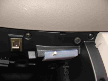
The glove compartment light is automatically operated On and Off as the hatch is opened and closed , for correct operation ensure that the compartment is not so full as to prevent the operation of the switch on the moulding of the hatch cover.
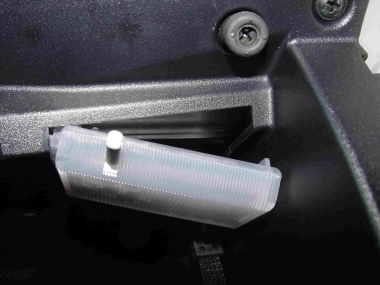
In the event of the lamp not lighting, ease the right hand side of the lens cover down square with the compartment.
When at 45% slide the cover away from its housing, this will come away complete with wiring so do not pull on the wiring. The connector is easily removed to enable easy bulb replacement. (festoon type bulb(C5W 12V 5W (F1) 2BL
Replace in reverse order having replaced the electrical connector slide the lens and wiring back into it is housing, ease the lens fully back into position then apply slight pressure to allow the lens to slide and secure aligned with the top of the glove compartment.