 If you have problems with starting as well as instrument cluster lights intermittently failing or the heater panel lights and blower failing to operate, then please read question 198 & 206 on page 3 before going further it my answer you question .
Hi lofty, I have a problem now that I can’t start the car. I have trailed through’ your comprehensive CD, but I cannot find a similar example of my fault. I hope you can help. The problem is that when trying to start the car, there is no display of any warning illumination, only the SRS light comes on. At this point the blower, wipers, windows all work but the horn and indicators do not. I have had the MAFS replaced at Mercedes one year ago, and the car has been fine since. I did notice a slight deterioration of the intensity of the panel lights over the past week, which made me think that a relay was may be on the point of burning out. I have checked all the fuses although I have not pulled them out, I checked for voltage across each one for consistency, so I guess it could still be ok on the connector. Any help is appreciated, and I will contact you if I find out what went down. Thanks,
That question and the symptoms mentioned are typical of an ignition switch problem, adjusting the key in the slot or even removing the bunch of keys on the same ring may temporarily allow you to start the car normally however in the long term the symptoms will reoccur and the switch will need to be replaced.
In the above instance the switch was replaced which cured the problem.
Thanks Ken for the Feed back.
Ignition Switch Connector.
When encountering defects on this connector isolating it as a defect is very difficult, the symptoms are not unlike those encountered when the starter motor goes defective.
One day the car will start normally the next it won't as with the starter few signs precede the problem.
Generally with the starter motors they play up and you can here the starter clicking which is the solenoid actuating but the motor does not turn the engine, However on this car invariably this is not the case and all remains silent.
The Ignition switch connector defect, is a slightly different problem in that the car will start after several tries but becomes more troublesome as time passes, until eventually the car will not start at all and having got you to your destination may not get you back.
This defect should not be confused with the locking mechanism, where doors will not unlock due to a key synchronisation problem or key fob battery problems
This is the component which is activated when the key is successfully turned in the ignition lock to the start position allowing power to be transmitted to the starter motor and other electrical components.
Where this component fails some icons may/will appear on the instrument cluster but not all, on other occasions only the SRS light will show and so on, where full contact is made all icons light as normal and the car will start.
I'm aware that 'Koolvin' a fellow owner whose wife drives the car suffered this problem for some time, until the time came that she was let down completely, something had to be done, and yet to take the car to a garage wasn't the answer because as is usually the case the car would perform normally when inspected by the mechanic, showing no defects, until of course it leaves the garage.
He therefore decided to investigate the problem further and having decided it was an electrical problem rather than mechanical decided to replace the ignition switch connector, which is the first electrical component in the line following the turning of the ignition key and like all moving parts is subject to wear
That sounds logical and simple enough, but alas that is not the case, a large amount of work has to be done just to get at this component although replacing it is straight forward enough.
WARNING
Now a word of warning if you are not mechanically minded and a regular DIY mechanic you would be well advised to leave this entire job to the professionals, not only is it an involved job it also requires the disconnection of the battery and the removal of the drivers air bag and steering wheel all of which must be done safely or severe injuries may be caused.
minimal but good quality tools are also required.
If you have decided to undertake this job then please follow all safety rules, and if you have a digital camera take photos as you go, this will assist you when it comes the reassembling the component parts, or of course you can print this page as use it for reference.
The item concerned in this case is the 'Ignition switch connector' Part number A168-5451004 cost £36.00 3/2009, with the part being available in this case off the shelf,(MB parts) So that's telling us all quite a lot, and yet I'm not aware it is a common problem.
It took the owner approx 1 hour to fit, and that tells me that he knows his way around the vehicle, it would take other owners I'm sure a lot longer .but time is not the main reason for DIY, one it can be because you like doing your own repairs or two it could be a case of cash flow , either is a valid reason for doing your repairs providing you work safely and know what you are doing.
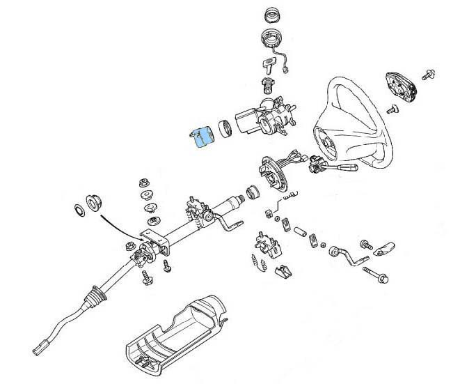
I have lightly coloured the offending component in the exploded diagram above, but it is not easily got at which of course is by design adding to the vehicle security, or ensuring you have to take your car to the garage I'm not sure which!. Remember failure of this switch can be either mechanical or electrical, to change the switch necessitates removing the :-
Drivers Airbag,
Steering wheel,
and clock-spring,
which is possible DIY providing you have the skills and good selection of high quality tools.
Before attempting this task disconnect the battery to isolate the drivers airbag.
If you do decide to tackle this job then you will need:-
1. Torque wrench (for leverage and correctly tightening the steering wheel securing screw)
2. 10"-12" 1/2 Extension bar
3. 10mm socket
4. 10mm Hexagonal bit (the steering wheel is secured with a 10mm wedge headed screw.)
5. Phillips screw driver fine and medium
6. 1 x T25-30mm 'Torx' bit approx 3" (75mm) in length, or a 'Torx' holder with a shaft no greater than 8mm in Dia.
7. Small wrench and suitable socket to hold bit.
8. Lock-tight for re-securing the steering wheel locking screw.
9. Small pen magnet for removing and returning the screws from combination switch recess holes.
10. 1 pair of pointed nose pliers .
From this point 90% of the procedure is now the same as for replacing/repairing the Combination Switch, but for ease of working I will duplicate the procedure on that page as nothing must be missed.
PREVENT ACCIDENTS
*When ever the need arises to remove the steering wheel or associated components it is necessary to Disconnect the Battery there is an air bag situated within the steering wheel assembly which if accidentally activated by short circuiting the contacts could cause serious/fatal injury.
REMEMBER there is a specific procedures set down on mypage 13 and page 300 in your Mercedes-Benz handbook for disconnecting the battery
Disconnecting = Negative terminal first
Re-connecting = Positive terminal first
Preparatory action prior to Removal of Steering Wheel.
1. Record /check availability of radio code as appropriate
2. Place keys in ignition,
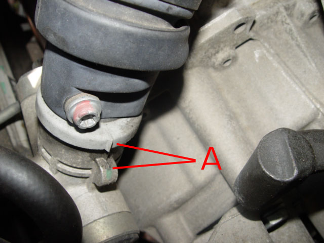 3. Align the road wheels as straight ahead. See markers on lower steering column components. A
 4. Remove the keys from the ignition and move the steering wheel slightly in either direction until the steering lock engages.
5. Chock at least one front wheel both front and rear, this will assist in maintaining the identical wheel alignment/position of the steering. This action is vital as the steering wheel MUST be replaced in an identical position as removed
6. Removing the steering wheel, the securing screw will be very tight, I found I had to use my torque wrench to get the leverage to undo this screw.
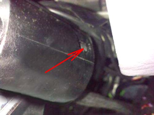
Replacing the steering wheel even one spline from it is original position can cause the deactivation of the direction indicator mechanism to fail as well as bring up the ESP/ABS light when re-assembled.
Look for the larger gap in the spine (Teeth ) of the column, if there is no markers ensure you introduce one before removing the steering wheel. The very small black line is the MB marker I also marked with white paint.
7. Disconnect the battery and secure the terminals to prevent them accidentally contacting the battery posts.
Disconnecting = Negative terminal first
PLEASE NOTE
Having disconnected the battery and removed the Drivers Air Bag DO NOT RECONNECT power until it has been refitted.
If you turn on the Ignition on without the Air bag connected you will get a SRS (Safety Restraint Systems)fault lamp light on the instrument cluster, the fault having be stored in the memory of the ECU, this cannot be deleted and hence the lamp turned off without visiting a MB workshop or MB independent garage where the fault code will need to be deleted using diagnostics equipment. This action will automatically delete the lamp.
Some of the more sophisticated EOBD hand held Diagnostics tools do now (08/2010) include this feature, so ask around before paying £50,00 plus which is what your likely to be charged by Mercedes-Benz Workshops. *Note
 Removing the Steering Wheel
1 Remove the two air bag securing screws located on the underside of the steering wheel Located at 9 & 3 o'clock underside of steering wheel.
* Support the 'Air Bag Unit' while undoing these fixings as the air bag will move away from the steering wheel; as the screws are undone.
* Two sizes have been mentioned by different people, both 'koovin's' are T30mine are T25 all 'Torx'(star) drive male bits, so make sure you find the correct size for your car, take care not to damage the screw head or you will never get them out!
2
Having completely removed these fixings
carefully lift the airbag off the steering wheel.
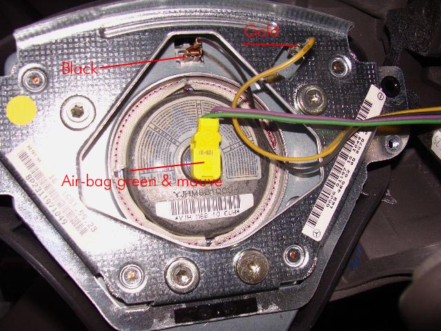
On the underside there is a central electrical connection. noting its position relative to the air bag unit this may be disconnected by gently levering away from the air bag with a flat bladed screw-driver, You will also have to remove the black and Gold wires, take care when removing the black wire connector.
I had problems and had to adjust the connector when replacing. It must be a good fit when replaced .
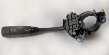
Note the difference in the design, the 2001 airbag in the left photo has the black & Gold wires attached to the air-bag
On the earlier models it appears they are attached to the horse shoe fitting forming part of the steering wheel.
Stow the air bag in a safe area positioned as to display the deployment area of the unit face up (store as situated when on steering column)
It must not be exposed to a temperatures of more than 100c.
* Note also the neat & tidy way the other wires are stowed, try to duplicate this when returning the Air bag unit.
* Having noted the position of the wiring connections/terminals connected to the air-bag or metal horse shoe, dependent on the year of A class you are working on. the wire in each case have different size spade connectors and so in theory cannot be replaced incorrectly, however confirm this is the case on your car before disconnecting.
If in doubt identify with a marker before disconnecting, or photograph if you have a digital camera.
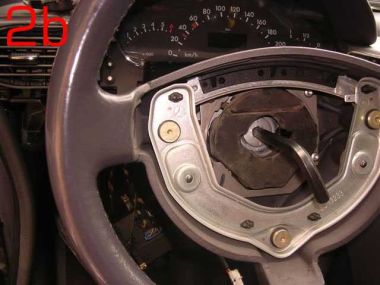 2b
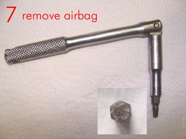
2b Using a 10mm 'Allen' key remove the centre counter sunk screw.
This should be found tight and you must re-torqued to 80Nm on re-assembly.
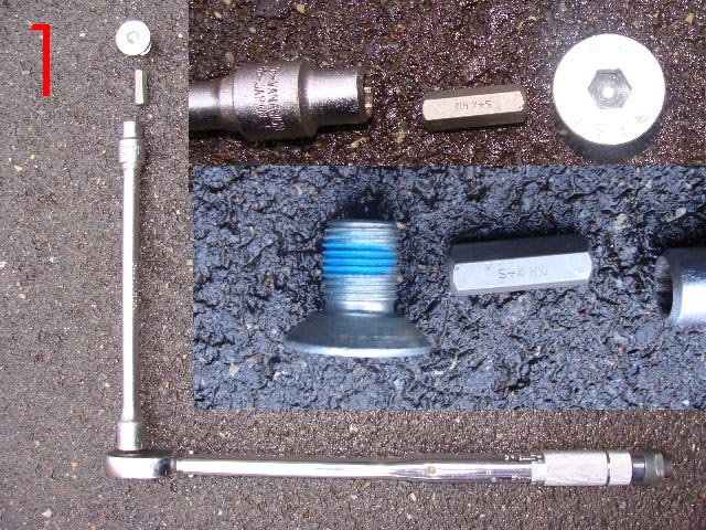
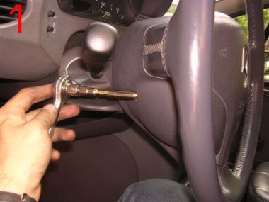
I had to use the tools shown in photo marked 1 above to remove my steering wheel locking screw, there was no way it was going to move with just an Allen key now matter how it was extended. as shown in this donated photo. A torque wrench should be used to ensure the correct torque when replacing.
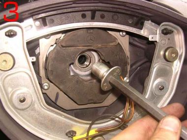 3
3It should be noted that due the the counter sunk screw being recessed an extension bar will be required complete with 10mm socket and 10mm hexagonal 'Allen' key. this method will prevent damage to the leather of the steering wheel.
Position your tools in such away as to avoid striking the windscreen when the screw gives (undoes).
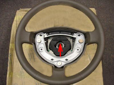 Before removing the steering wheel, Note that at 12 and 6 o-clock, (top and bottom) on the spline centre of the steering wheel, there are two recess/markers, D these must be re-aligned with the arrows/markers on the steering shaft/column, on re-assembly thereby ensuring the steering wheel is relocated precisely as removed.
Do not remove the steering wheel until you have made yourself aware of these makers. see 6 above for detail
 8
8The steering wheel can now be removed, take care that any wiring are not pulled or stretched.
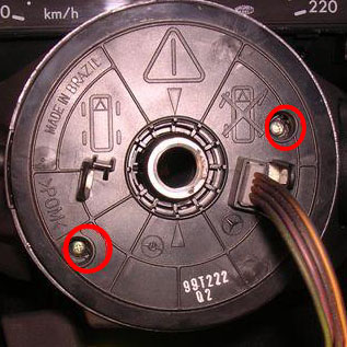
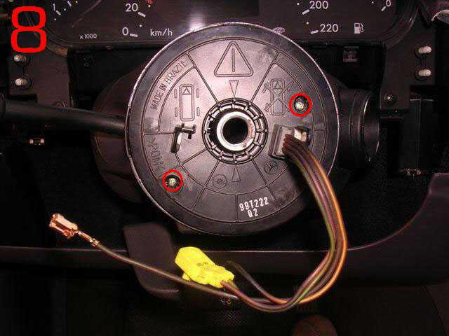
The clock spring will now be exposed.
This enlarged photo of the clock spring allows you to see the information on it . This should be followed or problems will arise when re-assembling.
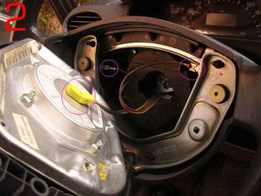
9. Removing the two ringed screws will allow you to remove the clock spring.
10. When doing so lift the clock spring straight up DO NOT twist or the 8 (2 X 4) contact/pins on the underside will become damaged.
* Do not tamper with the clock spring once removed, failure to observe this rule may result in it having to be rewound or replace at great cost.
Steering Angle Sensor
As the information says the steering angle sensor is clipped to the back of the clock spring. Unless there is a diagnosed problem with this unit then do not separate the two components.
I am not going to claim that I know what this component does, or what influence it is failure will have on the car or indicator warning lights, but as it is name implies it does indicate to the car at any given time, whilst the ignition is on; at what angle the wheels are positioned relative to travel.
Owners have also had to have it replaced where the SRS (air bag) indicator has been illuminated and cannot be extinguished and well as where the ESP/ABS lights have lit, and cannot be deleted using the reset procedure. Its cost for replacement purposes is approx £250.00, plus of course fitting.
Note there are many things to check before replacing the unit.
11
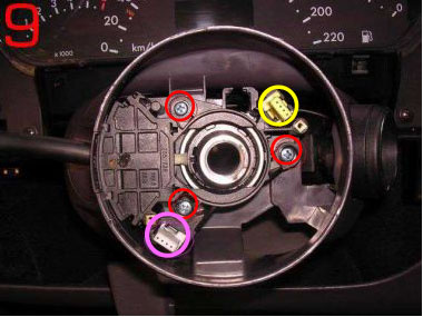
Removing the three ringed screws will allow you to remove the Combination Switch, the electrical connection should automatically unplug as it is removed.
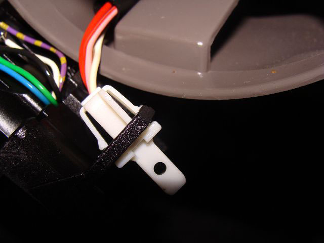
Having lifted the switch you will now have to release the white 4 pin block which is secured to the switch, using a pair of pointed nosed pliers hold the two spring loaded securing clips in allowing the connector to be released from the old switch . It will clip back into place on the new or replaced switch .
12. When replacing push the switch firmly into position to ensure a firm fit.
13.
When replacing the clock-spring, small contact pins engage into the yellow & white 4 pin connecters. A & B therefore great care must be taken when replacing this component to ensure it is aligned and square to the steering wheel.
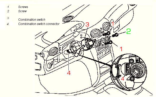
Note screw Numbered 2 (short screw) must be replaced in its original location or the steering lock may be damaged.(All 3 screws on my A160 2001 model were of the same length, to be safe simply replace the screws from where they were removed.
Paul
Had problems removing the sleeve, having overcome the problems encountered he has provided this information to assist others, Thank you Paul.
The ignition switch cover sleeve is held in place by three plastic spring clips moulded into the sleeve, the back one you simply can’t get to (and I didn’t even realise was there).
It simply levers out but It took me 3 hours of trying to gently lift the two I could see with miniature screwdrivers to finally realise it.
Taking care not to damage the black wire, using one’s left hand, one presses a small screwdriver between the 2 parts and using one’s right hand, pull the back of the sleeve (closest to the fascia) out and back towards you so the sleeve comes off parallel to the ignition switch. You do need to be quite firm with it as the clips hold on quite firmly.
Then the plastic steering column cover was difficult to get out and you have to be careful not to stress the black wire which is connected to the ignition switch cover sleeve and cannot be separated from it, as the ignition switch cover sleeve will not pass through the hole in the steering column cover so it’s left hanging on the wire.
In order to remove the steering column cover you have to alter the angle of the steering column to as low as it will go then press the right side of the cover towards the steering column so it will clear the fascia, then press it the other way so it will slide over the ignition switch housing (now exposed because the sleeve has been removed).
Once I realised I had to use a bit of muscle (advice from Mercedes mechanic) it was actually quite easy.
Removing the loom from the ignition switch connector was actually very easy once I realised that the two red rectangles did not play a part in removal process. After that it was really plain sailing and I it took a mere 20 minutes to put it all back together again. If I did it again I reckon it would not even take me an hour provided I started with the right tools.
Continue on this page for ignition switch problems
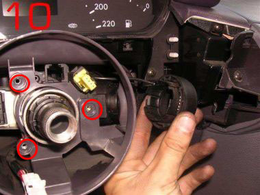
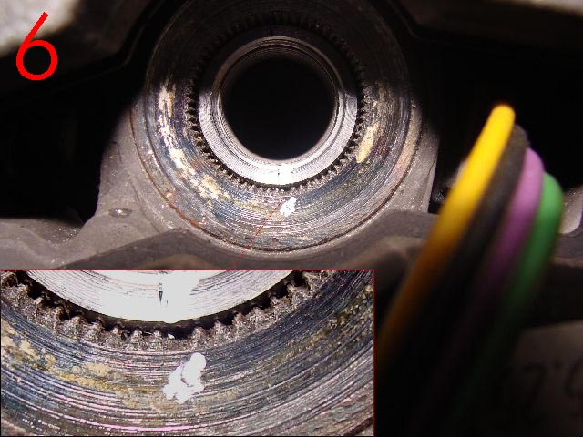
10
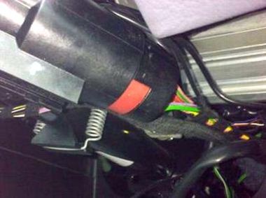
This photograph shows 'ignition switch' cover sleeve being removed The locking mechanism will remain attached to the column.
Not that there is a black wire 1 which is connected to the transponder coil, which in turn is connected to the DAS (Driver Authorization System)Control Module. It is the DAS module that is responsible for recognising the programmed ignition key when inserted in the ignition; either allowing the key to operate the ignition or not. It is also this device which plays a part in the re- synchronising of the Ignition keys.1 Make sure that is is not damaged or cut or on re-assembly your car will not start! For security reasons the location of the DAS module is not disclosed.
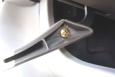
Where fitted. Release and lower the steering wheel height adjuster lever remove the 'Phillips' screw, remove the plastic handle.
You will now be able to remove the plastic steering column surround by easing it towards you .
This action will expose the steering column jacket-tube and ignition switch components with loom attached.
 Detach the loom assembly from the switch by depressing the two small lugs, one each side of the plastic carrier, these are best seen on the photos at the bottom of this page. .
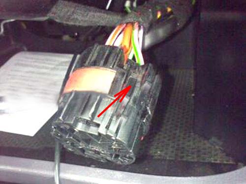
When handling the loom connector do so with care, the last thing you want are cables being pulled from the connector.
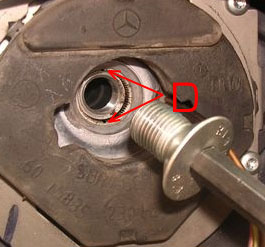
 To access and remove the defective switch connector, you will need to depress the two small lugs either side of the plastic sleeve (indicated by the arrow )at the same time sliding/removing switch connector from the lock.
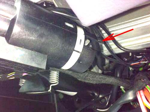
The arrow is pointing to the release clip which along with the one the other side has to be depressed to release the wiring loom.
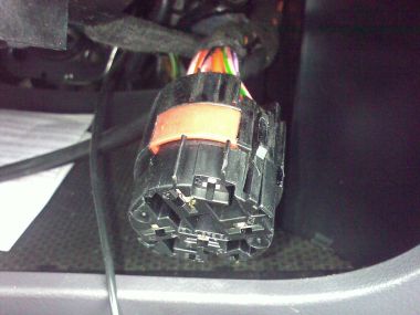
The switch can now be slid over the sleeve and away from the column.
Remove the defective switch, inspect the loom contacts to ensure that there are no signs of damage, corrosion, or scorching, (caused by overheating)
Fit the new switch connector.
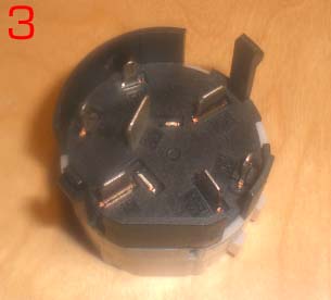
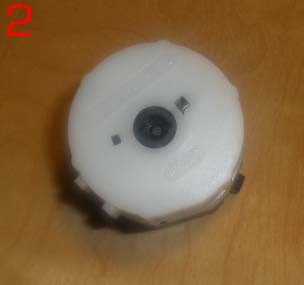
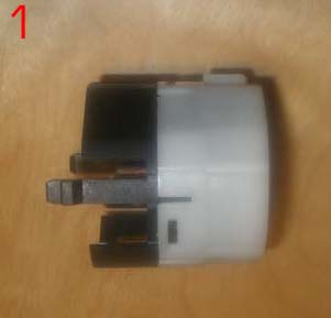 These three photos show the ignition contact switch, the white end going towards the ignition key lock.
The plastic clip which can be seen in 1 when correctly located is what hold the contact switch and loom connection firmly together, pay attention to ensure both sides fully lock when pushed together.
2 Shows the recess into which the spindle from the lock locates.
3 shows the connection spades that locate into the loom connector.
Having replaced the switch connector
On completion of the repair
Re-assemble all components in reverse order paying attention to detail.
Re-torque the steering wheel locking screw to 80Nm)
Before reconnecting battery terminals turn the main lighting switch to dipped or main beam, this reduces the risk of the Engine management light staying on after the battery is connected. Where this does occur , the light can only be deleted using diagnostics equipment. pre 2001 cars this can only be done by MB or a MB independent garage.
* Re-connect the battery *On completing re-assembly
Ensuring that the correct procedures are followed you are advised to follow the above procedure by turning the light switch to 'side lights' prior to battery connection.
Connect Positive terminal first followed by the negative terminal * Remove wheel chocks.
* Turn on ignition.
* Check the operation of the combination switch, check:-
Indicators
Head light dip switch
Head light flasher
Indicators, left and right,
Front Screen wash
Front Wipers, Alternative wiper speeds. (Carry out this test on the now wet wind-screen.)
* Check Fanfare/horn
* Check and correct clock, mypage.35.
* Enter radio Code as necessary
* Reset electric windows where fitted (front & Rear.) See page 13
* Reset ABS/ESP See page 13 for procedures. This is best done while slowly moving the car.
* On road test ensure that the indicators cancel when straightening up after left and right hand turns.
(If this is faulty then the steering wheel has been incorrectly aligned)
*Note there are instances where following the disconnecting and subsequent re-connection of the battery the engine management light fails to extinguish on start up, where this happens, (I do not know why some cars are prone to this but believe that it is caused by the power surge hitting the ECU as the battery connections are made.) the ECU management light fault, can only be deleted using diagnostics equipment. This does not necessarily mean going to Mercedes-Benz, as many garages now use diagnostics equipment which is compatible with petrol cars produced for the EC from 2001, Diesels 2004 if your car was constructed before those dates you may have to visit a MB workshop or MB independent garage to get the light deleted using 'Star' Diagnostics equipment.
However if the lighting switch is turned to at least side lights prior to fitting the battery the spike of power/surge hitting the ECU will be reduced which should prevent this problem in the first place.
I have not investigated this repair further but I suspect Mercedes-Bens Workshops would want your car for at least a couple of hours, which would with Vat cost approx £220 + parts +Parts, And they would want to put it on the diagnostics test prior to and following repair which for a short test would cost approx £60.00 plus Vat.
But please remember there are items that while doing this job you need to pay particular attention to. Correct torques for the steering wheel screw being just one, precise re-assembly of the steering wheel and components, clock spring etc, fail to get any of this 100% and you could finish up with more problems than you started and with and a large bill for putting it right by the garage. So please think about this before pulling your car apart.
I would like to thank 'koolvin' and also 'Raffa' both fellow owners of 'A' Class cars for their help in the production of this page, along with a number of the photographs.
As I have now had to replace the combination switch on my own car I have been able to contribute more detail and photos. Lofty
Next.
Back to Index,
Purchase DVD.
Please Make a Donation.