Component parts and Assembly
Steering Column, Steering Wheel & Related Components.See also page.49.
Special Note Avoid accidents When ever working on parts of the car fitted with AIR BAGS and SEAT BELT PRE-TENSIONERS DISCONNENECT THE BATTERY BEFORE COMMENCING WORK. Failure to do so could result in accidental activation of an Air Bag & the SRS warning light remaining ON when you next turn ON the ignition. This includes Door panels and steering wheels where air bags are stowed.
For combination Switch see mypage 71.
Please also read through page 49 before working on the steering
. Procedure common to both pre,& face lift models.
I would like to thank Rod (Ruffa Rodrigo) of Argentina for the photographs and input into this page.
note that they are of a pre-face lift, left hand drive car and there are differences from the face lift model.
Rod's problem was on his steering, where he has excessive movement both up and down and sideways on his steering wheel. As a result, and armed with information gleaned from the baby-benz.com, site as well as some e-mailed information from myself he stripped the steering and checked out the problem, which turned out to be insufficient torque being applied to the bearing situated in the top section of the steering column. Having re-torqued this setting his car is now OK.
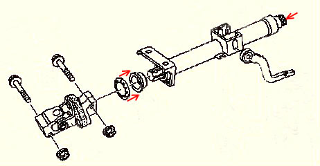
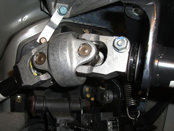
When the components in this section of the column are assembled with the top of the column secured, the UJ is slid onto the shaft which puts pressure on the jacket tube this has the effect of tightening the bearing, at which point the UJ is secured by the UJ bolt. In Rod's case the upper bolt had obviously loosened and had allowed the UJ and concaved retaining clip to slid which in turn took the torque of the bearing, with the result that excessive movement was felt at the steering wheel.
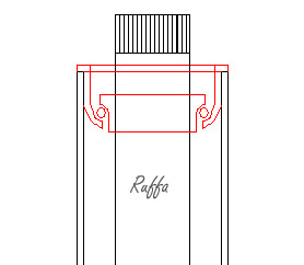
Rod's line drawing shows the bearing below, in situ at the top of the column.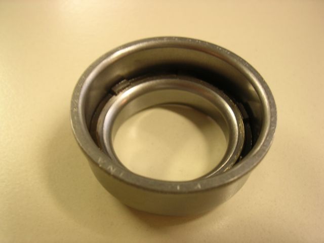
New bearing A126 981-00 251 Purchased but not required.
However Rod's problem could be turned into a photo opportunity and I asked him if would while, undertaking the job take some photographs which he agreed to do.
I am not going to cover the complete job undertaken but will cover the points common to both versions of the A Class.
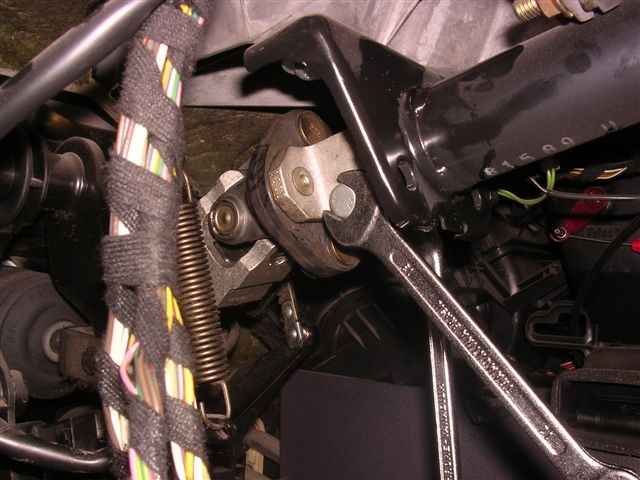
This photograph clearly indicated that Rod got to the seat of his problem and having slackened the UJ bolts was able to increase the torque/pressure on the bearing which cured his problem.
I have not added the numerous photos taken of removing the dash & components because Rod's car is pre-face lift and therefore the procedures are not appropriate to this model A160 Face-lift. My regular visitors will be aware I have tried to stay loyal to the A160 Face-lift model, and to break with the rule now would only confuse the situation.
I will however hold them on file and make them available if an owner suffers the same fate
I have therefore only covered the removal of the steering wheel, clock spring, and combination switch the procedures for which are common the both versions.
You are advised not to undertake repairs to this section of the vehicle unless you have a good working knowledge of the vehicle and have the necessary technical information available and to hand.
This e-mail was received Sept 08 from an owner with the same problem and was able to sort the job himself, with of course the help of 'Rod's' information received much earlier
Thanks for a brilliant web-site, Lofty. Your "aclassinfo.co.uk" pages are magic treasure-trove for me. I will add his mail which may help others if they have the same problem.
I was very excited to spot your page 50 - Steering Wheel & Related Components - and especially the information about the loose-bearing problem and fix of Ruffa Rodrigo from Argentina, which helped me save a huge wad of cash for a new steering column, which seemed to be the only Mercedes answer to my situation.
My problem seemed similar to Rod's - I had some sideways play in the steering column, although strangely none in the steering itself, as the vehicle steered perfectly. The steering wheel had no rotational play at all, it was nice and tight - even the tiniest rotational pressure on the steering wheel while driving reached the wheels, and the vehicle turned. However, when you waggled the steering wheel without turning it, it moved a little, from side to side or up and down, with also a bit of fore and aft movement towards my feet and chest, and a gentle clunking feeling when you did these things.
My favourite Rottweiler MOT tester pointed this out, but said he would not at present call this a steering fault because it wasn't, yet, but recommended attention because it would probably get worse rather than better, and then it probably would become an MOT fault. I think he was being nice this year, but wouldn't be next time.
The car is my lady's A160 petrol Long Wheel base May 2003 registered "03" - Face-Lift version of the A-class Elegance Auto, 27,000 miles total - surely it can't be worn steering at this low mileage?
Well, on closer inspection, when I waggled the Universal Joint (UJ) down beside the brake pedal, the UJ itself felt quite taut. However, the bearing fixing, just uphill behind the plastic document holder under-panel towards the driver, could clearly be felt and seen to be loose and wobbly - apparently the same problem as experienced by Rod.
For interest, my upper steering UJ itself is slightly different in my Face-Lift model from the pre-Face-Lift diagrams you included on your pages 49 and 50, in that this later UJ has integral riveted bolts at the connection downwards to the lower steering shaft, and you cannot undo this.
That makes no difference, because the UJ upper clamp-joint is still tightened by a 13mm removable nut and bolt at its top, as in your diagrams, just not as shown also at the UJ bottom. So my inkling was that I would still be able to slacken this UJ clamp bolt and move the clamp and UJ uphill, compressing the loose bearing, and then retighten the clamp bolt again.
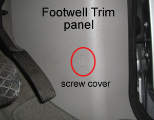
Well I eventually gained access to the wobbly bearing, which is well hidden behind the plastic document tray under the steering column and by the steering column cover as well. It was hard work taking off the plastic doc tray, held among other things by a hidden screw and two strong clips under the door pillar rubber seal on the right of the cockpit, behind the right-wall foot well plastic inboard kick-cover. The secret of gaining access to the hidden screw was the racetrack-shaped small plastic cover in the middle of the foot well kick-cover. This small cover is just clipped-in, and when tapped at one corner, simply fell out and revealed its own hidden screw, which allowed removal of the kick-cover which gave access to that doc-cover right-hand hidden screw behind that door seal.
Taking in the slack in the wobbly bearing was difficult - the UJ upper clamp wasn't keen to move. I had to lever apart the sides of the clamp which the 13mm bolt had held closed for five years. I then used a specially-twisted steel coat-hanger extension fitted onto a wind-up furniture screw-clamping tool, and this combination was able to bring enough pressure to bear to drag closely together the loosened UJ end and the steering column.
While held under pressure, the 13mm bolt was re-tightened, and when my makeshift pressure was released the bearing was no longer wobbly but taut and centralised. It no longer has any play, lateral or fore-and-aft, in it, and rotates freely, as presumably it was designed to do. Job done!
We are probably all left wondering why a vital steering column bearing like this should work loose in the first place, and be designed with no simple tightening mechanism of its own, as well as being un-greased and open to contamination - but that's another story.
Well, Lofty, I am so grateful for the information on your exceptional web site, which as you can tell has made it possible for me to have the confidence to fix something that sounded like it might only be cured by fitting an expensive new major component, the steering column. So I am overjoyed, and hope this account will help your readers.
 Very best regards
Robert
I went back to Robert with a few questions after all he's done the job so is well qualified to offer help to others through my site.
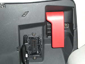
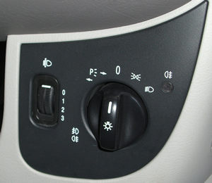
"did you have to remove the black undertray if so did you release the screws on the OBD2 connector or did it release with that tray?" Yes - the black undertray had to come out. Yes, the 2 screws on the On-Board Diagnostic connector had to come out too. So did the single screw holding the red Bonnet Release lever. So did the simple pull-out black trim around the light swtches. So did the two screws holding that lighting multiswitch, and the clips above and below the headlight level adjuster knob had to be released. So did the fascia vent cover and knob assembly on the right, which just levers out then pulls out easily, and will later be just a simple push fit back in again into its plastic spacer which connects it to the pliable air tube feeding it from behind.
 The secret to getting that undertray out after undoing the screws you had spotted, was the hidden screw on the right into the door pillar, under the door trim. First pull back the black rubber seal on the vertical part of the door pillar, it comes out and goes back really easily, exposing the end of the door trim panel. You have to remove the panel which is part of that door trim, it is to the right of the footwell, a kick-panel beside the accelerator pedal. There is another hidden screw holding that panel, covered by an inconspicuous-looking racetrack-shaped flat plastic cover which looks as if it is just part of the moulded kick-cover, not an obviously removeable clip-in piece at all. However, when tapped at the side or levered with a fine point this cover falls out to reveal its holding screw beneath. When that screw is removed, the panel and trim up to the door pillar come loose, and under that trim on the door pillar is exposed the final screw holding the black undertray.
Bear in mind that these last two photgraphs are taken from a mirror reflection and therefore appear upsidedown!t
further Information can also be obtained by visiting this link:-
baby-benz.com
Thank you Robert for the additional photographs which make it far easier to understand the points you make.
PREVENT ACCIDENTS *When ever the need arises to work on the steering wheel or associated components it is necessary to Disconnect the Battery there is an air bag situated within the steering wheel assembly which if accidentally activated by short circuiting the contacts could cause serious injury.
REMEMBER there is a specific procedures set down on mypage 13 and page 300 in your Mercedes-Benz handbook for disconnecting the battery
Disconnecting = Negative terminal first
Re-connecting = Positive terminal first
The Steering Wheel my need to be removed for a number of reasons,* Steering Column Problems
* Steering Angle Sensor Defects
* Clock spring problems
* Replacement of Combination Switch due to defects
Preparatory action prior to Removal of Steering Wheel. * Place keys in ignition,
* Align the road wheels as straight ahead as is possible.
* Remove the keys from the ignition and move the steering wheel slightly in either direction until the steering lock engages.
* Chock one front wheel front and rear, this will assist in maintaining the identical wheel alignment/position of the steering.
* Replacing the steering wheel even one spline from it is original position can cause the deactivation of the direction indicator mechanism to fail.
* Disconnect the battery and secure the terminals to prevent them accidentally contacting the battery posts.
*Note Do not attempt to turn the Ignition keys in the switch once the battery is disconnected.
If you do decide to tackle this job then you will need the following tools just to remove the steering wheel. :-
1. Torque wrench (for leverage and correctly tightening the steering wheel securing screw)
2. 10"-12" 1/2 Extension bar
3. 10mm socket
4. 10mm Hexagonal bit (the steering wheel is secured with a 10mm wedge headed screw.)
5. Phillips screw driver fine and medium
6. 1 x T25-30mm 'Torx' bit approx 3" (75mm) in length, or a 'Torx' holder with a shaft no greater than 8mm in Dia.
7. Small wrench and suitable socket to hold bit.
8. Locktight for re-securing the steering wheel locking screw.
9. Small pen magnet for removing and returning the screws from combination switch recess holes.
10. 1 pair of pointed nose pliers .
From this point 90% of the procedure is now the same as for replacing/repairing the Combination Switch, but for ease of working I will duplicate the procedure on that page as nothing must be missed.
PREVENT ACCIDENTS
*When ever the need arises to remove the steering wheel or associated components it is necessary to Disconnect the Battery there is an air bag situated within the steering wheel assembly which if accidentally activated by short circuiting the contacts could cause serious/fatal injury.
REMEMBER there is a specific procedures set down on mypage 13 and page 300 in your Mercedes-Benz handbook for disconnecting the battery
Disconnecting = Negative terminal first
Re-connecting = Positive terminal first
Preparatory action prior to Removal of Steering Wheel.
1. Record /check availability of radio code as appropriate
2. Place keys in ignition,
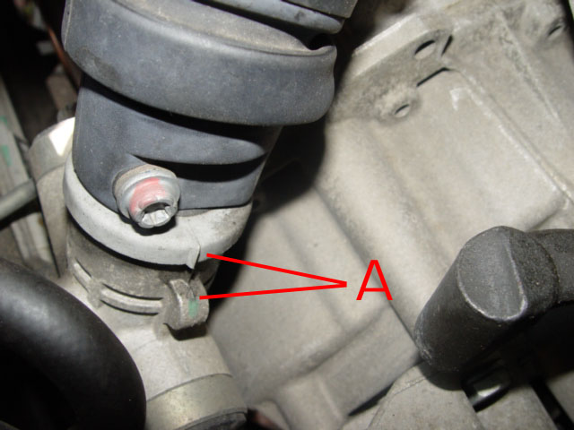 3. Align the road wheels as straight ahead. See markers on lower steering column components. A
4. Remove the keys from the ignition and move the steering wheel slightly in either direction until the steering lock engages.
5. Chock at least one front wheel both front and rear, this will assist in maintaining the identical wheel alignment/position of the steering. This action is vital as the steering wheel MUST be replaced in an identical position as removed
6. Removing the steering wheel, the securing screw will be very tight, I found I had to use my torque wrench to get the leverage to undo this screw.
Replacing the steering wheel even one spline from it is original position can cause the deactivation of the direction indicator mechanism to fail as well as bring up the ESP/ABS light when re-assembled.
Look for the larger gap in the spine (Teeth ) of the column, if there is no markers ensure you introduce one before removing the steering wheel. The very small black line is the MB marker I also marked with white paint.
7. Disconnect the battery and secure the terminals to prevent them accidentally contacting the battery posts.
Disconnecting = Negative terminal first
PLEASE NOTE
Having disconnected the battery and removed the Drivers Air Bag DO NOT RECONNECT power until it has been refitted.
If you turn on the Ignition on without the Air bag connected you will get a SRS (Safety Restraint Systems)fault lamp light on the instrument cluster, the fault having be stored in the memory of the ECU, this cannot be deleted and hence the lamp turned off without visiting a MB workshop or MB independent garage where the fault code will need to be deleted using diagnostics equipment. This action will automatically delete the lamp.
Some of the more sophisticated EOBD hand held Diagnostics tools do now (08/2010) include this feature, so ask around before paying £50,00 plus which is what your likely to be charged by Mercedes-Benz Workshops. *Note Do not attempt to turn the Ignition keys in the lock once the battery is disconnected.
 Removing the Steering Wheel
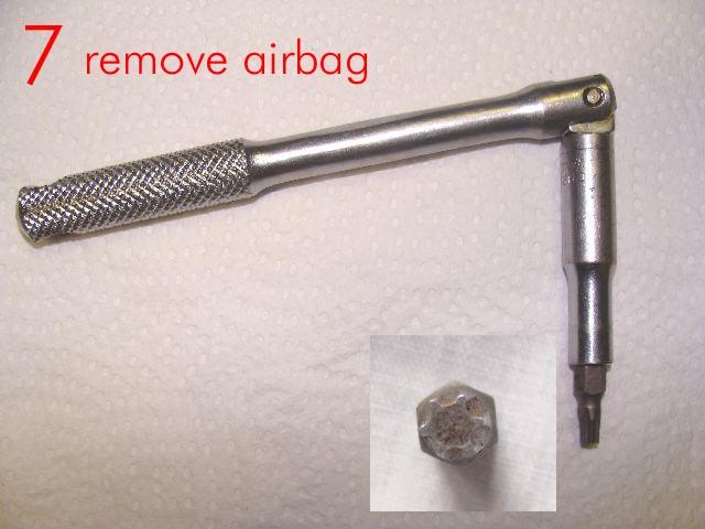
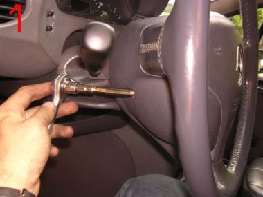
1 Remove the two air bag securing screws located on the underside of the steering wheel Located at 9 & 3 o'clock underside of steering wheel.
* Support the 'Air Bag Unit' while undoing these fixings as the air bag will move away from the steering wheel; as the screws are undone.
* Two sizes have been mentioned by different people, both 'koovin's' are T30mine are T25 all 'Torx'(star) drive male bits, so make sure you find the correct size for your car, take care not to damage the screw head or you will never get them out!
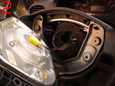
2
Having completely removed these fixings
carefully lift the airbag off the steering wheel.
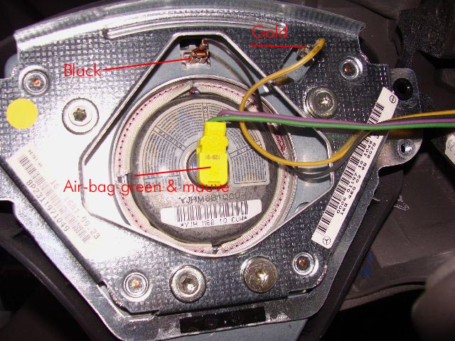
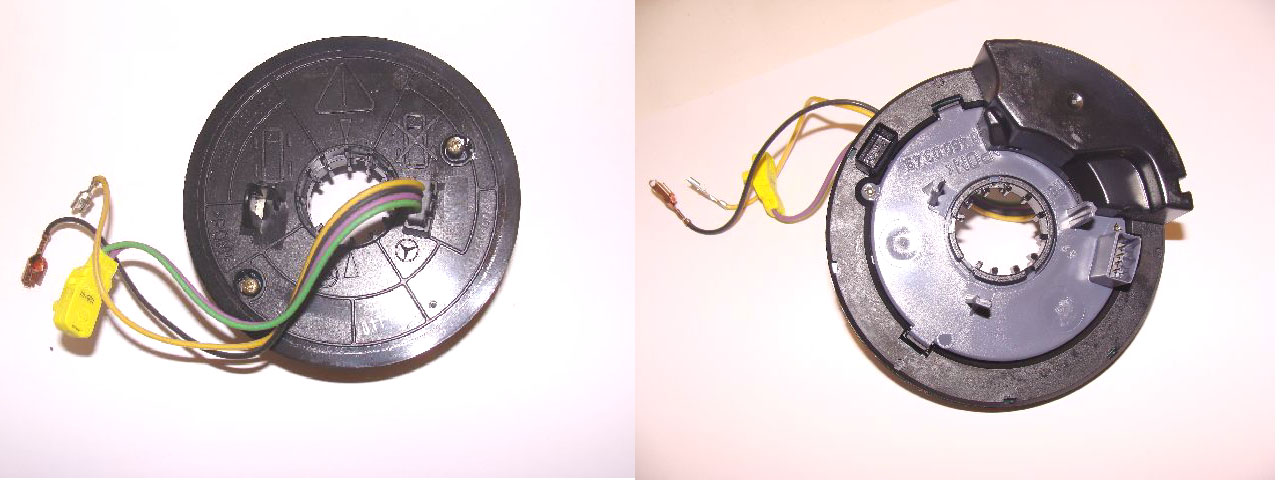
On the underside there is a central electrical connection. noting its position relative to the air bag unit this may be disconnected by gently levering away from the air bag with a flat bladed screw-driver, You will also have to remove the black and Gold wires, take care when removing the black wire connector.
I had problems and had to adjust the connector when replacing. It must be a good fit when replaced .
Note the difference in the design, the 2001 airbag in the left photo has the black & Gold wires attached to the air-bag
On the earlier models it appears they are attached to the horse shoe fitting forming part of the steering wheel.
Stow the air bag in a safe area positioned as to display the deployment area of the unit face up (store as situated when on steering column)
It must not be exposed to a temperatures of more than 100c.
* Note also the neat & tidy way the other wires are stowed, try to duplicate this when returning the Air bag unit.
* Having noted the position of the wiring connections/terminals connected to the air-bag or metal horse shoe, dependent on the year of A class you are working on. the wire in each case have different size spade connectors and so in theory cannot be replaced incorrectly, however confirm this is the case on your car before disconnecting.
If in doubt identify with a marker before disconnecting, or photograph if you have a digital camera.
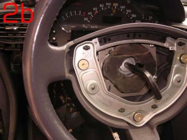 2b
2b
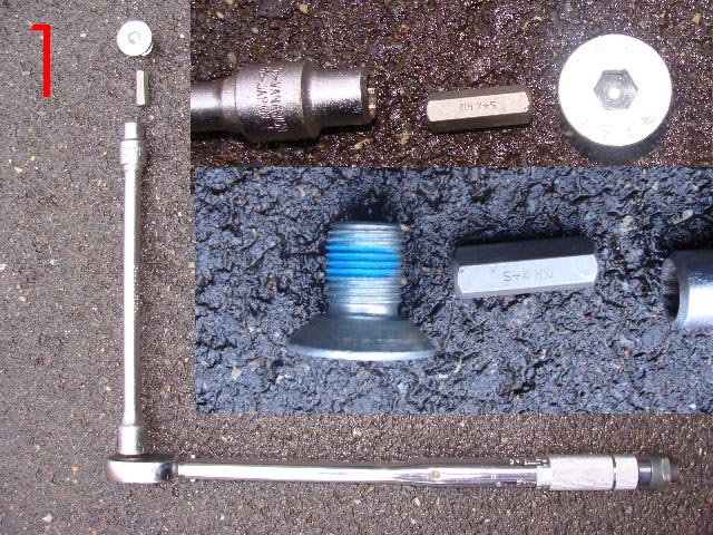
Using a 10mm 'Allen' key remove the centre counter sunk screw.
This should be found tight and you must re-torqued to 80Nm on re-assembly.
I had to use the tools shown in photo marked 1 above to remove my steering wheel locking screw, there was no way it was going to move with just an Allen key now matter how it was extended. as shown in this donated photo. A torque wrench should be used to ensure the correct torque when replacing.
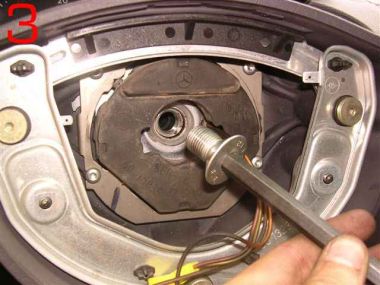 3
3
It should be noted that due the the counter sunk screw being recessed an extension bar will be required complete with 10mm socket and 10mm hexagonal 'Allen' key. this method will prevent damage to the leather of the steering wheel.
Position your tools in such away as to avoid striking the windscreen when the screw gives (undoes).
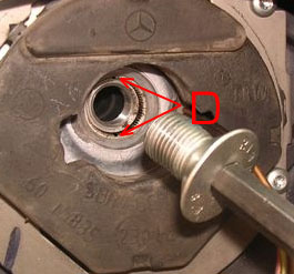
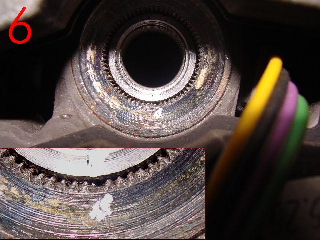
 Before removing the steering wheel, Note that at 12 and 6 o-clock, (top and bottom) on the spline centre of the steering wheel, there are two recess/markers, D these must be re-aligned with the arrows/markers on the steering shaft/column, on re-assembly thereby ensuring the steering wheel is relocated precisely as removed.
Do not remove the steering wheel until you have made yourself aware of these makers. see 6 above for detail
 8
8
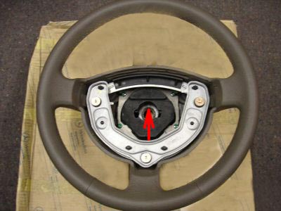
The steering wheel can now be removed, take care that any wiring are not pulled or stretched.
The clock spring will now be exposed.
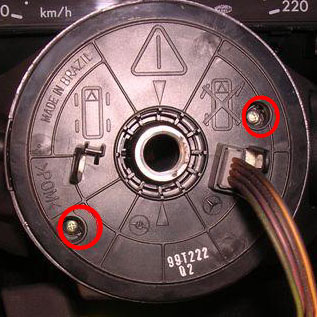
This enlarged photo of the clock spring allows you to see the information on it . This should be followed or problems will arise when re-assembling.
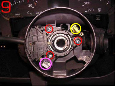
9. Removing the two ringed screws will allow you to remove the clock spring.
10. When doing so lift the clock spring straight up DO NOT twist or the 8 (2 X 4) contact/pins on the underside will become damaged.
* Do not tamper with the clock spring once removed, failure to observe this rule may result in it having to be rewound or replace at great cost.
Steering Angle Sensor
As the information says the steering angle sensor is clipped to the back of the clock spring. Unless there is a diagnosed problem with this unit then do not separate the two components.
I am not going to claim that I know what this component does, or what influence it is failure will have on the car or indicator warning lights, but as it is name implies it does indicate to the car at any given time, whilst the ignition is on; at what angle the wheels are positioned relative to travel.
Owners have also had to have it replaced where the SRS (air bag) indicator has been illuminated and cannot be extinguished and well as where the ESP/ABS lights have lit, and cannot be deleted using the reset procedure. Its cost for replacement purposes is approx £250.00, plus of course fitting.
Note there are many things to check before replacing the unit.
11
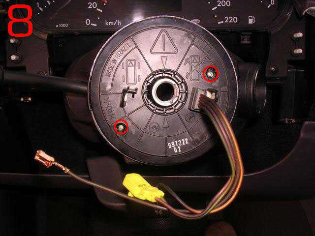
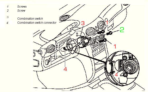
Removing the three ringed screws will allow you to remove the Combination Switch, the electrical connection should automatically unplug as it is removed.
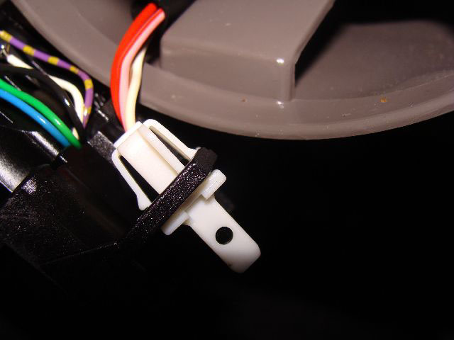
Having lifted the switch you will now have to release the white 4 pin block which is secured to the switch, using a pair of pointed nosed pliers hold the two spring loaded securing clips in allowing the connector to be released from the old switch . It will clip back into place on the new or replaced switch .
12. When replacing push the switch firmly into position to ensure a firm fit.
13.
When replacing the clock-spring, small contact pins engage into the yellow & white 4 pin connecters. A & B therefore great care must be taken when replacing this component to ensure it is aligned and square to the steering wheel.
Note screw Numbered 2 (short screw) must be replaced in its original location or the steering lock may be damaged.(All 3 screws on my A160 2001 model were of the same length, to be safe simply replace the screws from where they were removed.
Steering Angle Sensor
As the information says the steering angle sensor is clipped to the back of the clock spring. Unless there is a diagnosed problem with this unit then do not separate the two components.
I am not going to claim that I know precisely what this component does, or what influence it is failure will have on the car or indicator warning lights. But as it is name implies it does indicate to the car at any given time, whilst the ignition is on; at what angle the front wheels are positioned.
Owners have also had to have it replaced where the SRS (air bag) indicator has been illuminated and cannot be extinguished and well as where the ESP/ABS lights have lit, and cannot be deleted using the reset procedure. Its cost for replacement purposes is approx £250.00, plus of course fitting.
Re-setting the steering angle sensor is carried out by turning the steering wheel fully left and right after re-assembly, this action should extinguish the ESP/ABS indicator on the dash. Further details are available on mypage 35
9
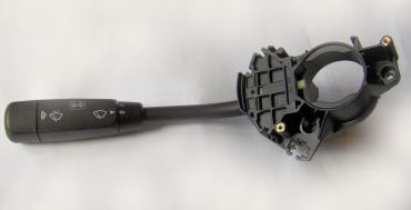
Removing the three ringed screws will allow you to remove the Combination Switch, which operated (Dip, Head light flasher, Wipers, Indicators, Windscreen Wipers/Washer pump) the electrical connection should automatically unplug as it is removed. However take care you may need to assist its removal using a small screwdriver or similar tool.
* When replacing push the connection to ensure a firm fit.
* A Word of Warning, one owner encountered extreme problems when having fitted a new Combination switch discovered that the ESP/ABS light would not go out when the system was reset. To cut a long story short the problem turned out to be a slight modification to the combination switch that required the use of spacer washers to be fitted to overcome the problem . So if you are replacing components on your car always be prepared to provide the chassis and engine numbers in an effort to obtain the correct parts for your car. And get a firm quote in writing from the garage for such work. In this case the owner finished up with a bill but with the original fault still on his car.
the fault was finally located & corrected by his local Independent mechanic.
When replacing the clock-spring small pins engage into the yellow & white 4 pin connecters. A & B therefore great care must be taken when replacing this component
Transponder Key recognition programme/DAS control module.
While we have the steering assembly stripped, lets take a look at the transponder set up. There should be no need to remove this component unless there is a ignition key recognition system failure, where the car fails to start and the system will not re-programme the ignition keys when following the correct re-programming procedure. see mypage 35.
10
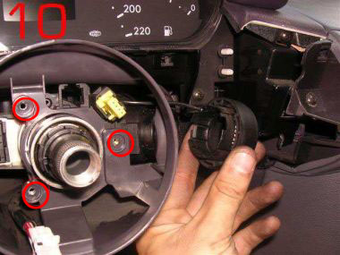
This photograph shows ignition switch cover sleeve being removed The ignition switch locking mechanism will remain attached to the column.
Not that there is a black wire 1 which is connected to the transponder coil, which in turn is connected to the DAS (Driver Authorization System)Control Module. It is the DAS module that is responsible for recognising the programmed ignition key when inserted in the ignition; either allowing the key to operate the ignition or not. It is also this device which plays a part in the re- synchronising of the Ignition keys.1 Make sure that is is not damaged or cut or on re-assembly your car will not start! For security reasons the location of the DAS module is not disclosed.
On completion of the repair
Re-assemble all components in reverse order paying attention to detail.
Re-torque the steering wheel locking screw to 80Nm)
Before reconnecting battery terminals turn the main lighting switch to dipped or main beam, this reduces the risk of the Engine management light staying on after the battery is connected. Where this does occure , the light can only be deleted using diagnostics equipement.pre 2001 cars this can only be done by MB or a MB independent garage.
* Re-connect the battery *On completing re-assembly
Ensuring that the correct procedures are followed you are advised to follow the above procedure by turning the light switch to 'side lights' prior to battery connection.
Connect Positive terminal first followed by the negative terminal * Remove wheel chocks.
* Turn on ignition.
* Check the operation of the combination switch, check:-
Indicators
Head light dip switch
Head light flasher
Indicators, left and right,
Front Screen wash
Front Wipers, Alternative wiper speeds. (Carry out this test on the now wet wind-screen.)
* Check Fanfare/horn
* Check and correct clock, mypage.35.
* Enter radio Code as necessary
* Reset electric windows where fitted (front & Rear.) See page 13
* Reset ABS/ESP See page 13 for procedures. This is best done while slowly moving the car.
* On road test ensure that the indicators cancel when straightening up after left and right hand turns.
(If this is faulty then the steering wheel has been incorrectly aligned)
*Note there are instances where following the disconnecting and subsequent re-connection of the battery the engine management light fails to extinguish on start up, where this happens, (I do not know why some cars are prone to this but believe that it is caused by the power surge hitting the ECU as the battery connections are made.) the ECU management light fault, can only be deleted using diagnostics equipment. This does not necessarily mean going to Mercedes-Benz, as many garages now use diagnostics equipment which is compatible with petrol cars produced for the EC from 2001, Diesels 2004 if your car was constructed before those dates you may have to visit a MB workshop or MB independent garage to get the light deleted using 'Star' Diagnostics equipment.
However if the lighting switch is turned to at least side lights prior to fitting the battery the spike of power/surge hitting the ECU will be reduced which should prevent this problem in the first place.
Having re-assembled the components parts, and connected the battery always test all services that have been affected by the job undertaken to confirm everthing is working and safe.
I have not investigated this repair further but I suspect Mercedes-Bens Workshops would want your car for at least an hour, which would with Vat cost approx £110+ parts Plus they would want to put it on the diagnostics test prior to and following repair which for a short test would cost approx £60.00 plus Vat.
But please remember there are items that while doing this job you need to pay particular attention to. Correct torques for the steering wheel screw being just one, precise re-assembly of the steering wheel and components, clock spring etc, fail to get any of this 100% and you could finish up with more problems than you started and with and a large bill for putting it right by the garage. So please think about this before pulling your car apart.
I would like to thank 'koolvin' and also 'Raffa' both fellow owners of 'A' Class cars for their help in the production of this page, along with a number of the photographs.
As I have now had to replace the combination switch on my own car I have been able to contribute more detail and photos. Lofty
Next.
Back to Index,
Purchase DVD.
Please Make a Donation.

note that they are of a pre-face lift, left hand drive car and there are differences from the face lift model.
Rod's problem was on his steering, where he has excessive movement both up and down and sideways on his steering wheel. As a result, and armed with information gleaned from the baby-benz.com, site as well as some e-mailed information from myself he stripped the steering and checked out the problem, which turned out to be insufficient torque being applied to the bearing situated in the top section of the steering column. Having re-torqued this setting his car is now OK.
When the components in this section of the column are assembled with the top of the column secured, the UJ is slid onto the shaft which puts pressure on the jacket tube this has the effect of tightening the bearing, at which point the UJ is secured by the UJ bolt. In Rod's case the upper bolt had obviously loosened and had allowed the UJ and concaved retaining clip to slid which in turn took the torque of the bearing, with the result that excessive movement was felt at the steering wheel.
Rod's line drawing shows the bearing below, in situ at the top of the column.
New bearing A126 981-00 251 Purchased but not required.
However Rod's problem could be turned into a photo opportunity and I asked him if would while, undertaking the job take some photographs which he agreed to do.
I am not going to cover the complete job undertaken but will cover the points common to both versions of the A Class.
This photograph clearly indicated that Rod got to the seat of his problem and having slackened the UJ bolts was able to increase the torque/pressure on the bearing which cured his problem.
I have not added the numerous photos taken of removing the dash & components because Rod's car is pre-face lift and therefore the procedures are not appropriate to this model A160 Face-lift. My regular visitors will be aware I have tried to stay loyal to the A160 Face-lift model, and to break with the rule now would only confuse the situation.
I will however hold them on file and make them available if an owner suffers the same fate
I have therefore only covered the removal of the steering wheel, clock spring, and combination switch the procedures for which are common the both versions.
You are advised not to undertake repairs to this section of the vehicle unless you have a good working knowledge of the vehicle and have the necessary technical information available and to hand.
This e-mail was received Sept 08 from an owner with the same problem and was able to sort the job himself, with of course the help of 'Rod's' information received much earlier
Thanks for a brilliant web-site, Lofty. Your "aclassinfo.co.uk" pages are magic treasure-trove for me. I will add his mail which may help others if they have the same problem.
I was very excited to spot your page 50 - Steering Wheel & Related Components - and especially the information about the loose-bearing problem and fix of Ruffa Rodrigo from Argentina, which helped me save a huge wad of cash for a new steering column, which seemed to be the only Mercedes answer to my situation.
My problem seemed similar to Rod's - I had some sideways play in the steering column, although strangely none in the steering itself, as the vehicle steered perfectly. The steering wheel had no rotational play at all, it was nice and tight - even the tiniest rotational pressure on the steering wheel while driving reached the wheels, and the vehicle turned. However, when you waggled the steering wheel without turning it, it moved a little, from side to side or up and down, with also a bit of fore and aft movement towards my feet and chest, and a gentle clunking feeling when you did these things.
My favourite Rottweiler MOT tester pointed this out, but said he would not at present call this a steering fault because it wasn't, yet, but recommended attention because it would probably get worse rather than better, and then it probably would become an MOT fault. I think he was being nice this year, but wouldn't be next time.
The car is my lady's A160 petrol Long Wheel base May 2003 registered "03" - Face-Lift version of the A-class Elegance Auto, 27,000 miles total - surely it can't be worn steering at this low mileage?
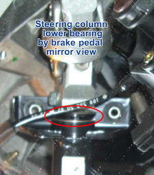
Well, on closer inspection, when I waggled the Universal Joint (UJ) down beside the brake pedal, the UJ itself felt quite taut. However, the bearing fixing, just uphill behind the plastic document holder under-panel towards the driver, could clearly be felt and seen to be loose and wobbly - apparently the same problem as experienced by Rod.
For interest, my upper steering UJ itself is slightly different in my Face-Lift model from the pre-Face-Lift diagrams you included on your pages 49 and 50, in that this later UJ has integral riveted bolts at the connection downwards to the lower steering shaft, and you cannot undo this.
That makes no difference, because the UJ upper clamp-joint is still tightened by a 13mm removable nut and bolt at its top, as in your diagrams, just not as shown also at the UJ bottom. So my inkling was that I would still be able to slacken this UJ clamp bolt and move the clamp and UJ uphill, compressing the loose bearing, and then retighten the clamp bolt again.
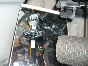
Well I eventually gained access to the wobbly bearing, which is well hidden behind the plastic document tray under the steering column and by the steering column cover as well. It was hard work taking off the plastic doc tray, held among other things by a hidden screw and two strong clips under the door pillar rubber seal on the right of the cockpit, behind the right-wall foot well plastic inboard kick-cover. The secret of gaining access to the hidden screw was the racetrack-shaped small plastic cover in the middle of the foot well kick-cover. This small cover is just clipped-in, and when tapped at one corner, simply fell out and revealed its own hidden screw, which allowed removal of the kick-cover which gave access to that doc-cover right-hand hidden screw behind that door seal.
Taking in the slack in the wobbly bearing was difficult - the UJ upper clamp wasn't keen to move. I had to lever apart the sides of the clamp which the 13mm bolt had held closed for five years. I then used a specially-twisted steel coat-hanger extension fitted onto a wind-up furniture screw-clamping tool, and this combination was able to bring enough pressure to bear to drag closely together the loosened UJ end and the steering column.
While held under pressure, the 13mm bolt was re-tightened, and when my makeshift pressure was released the bearing was no longer wobbly but taut and centralised. It no longer has any play, lateral or fore-and-aft, in it, and rotates freely, as presumably it was designed to do. Job done!
We are probably all left wondering why a vital steering column bearing like this should work loose in the first place, and be designed with no simple tightening mechanism of its own, as well as being un-greased and open to contamination - but that's another story.
Well, Lofty, I am so grateful for the information on your exceptional web site, which as you can tell has made it possible for me to have the confidence to fix something that sounded like it might only be cured by fitting an expensive new major component, the steering column. So I am overjoyed, and hope this account will help your readers.
Very best regardsRobert
I went back to Robert with a few questions after all he's done the job so is well qualified to offer help to others through my site.
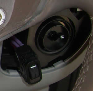
"did you have to remove the black undertray if so did you release the screws on the OBD2 connector or did it release with that tray?" Yes - the black undertray had to come out. Yes, the 2 screws on the On-Board Diagnostic connector had to come out too. So did the single screw holding the red Bonnet Release lever. So did the simple pull-out black trim around the light swtches. So did the two screws holding that lighting multiswitch, and the clips above and below the headlight level adjuster knob had to be released. So did the fascia vent cover and knob assembly on the right, which just levers out then pulls out easily, and will later be just a simple push fit back in again into its plastic spacer which connects it to the pliable air tube feeding it from behind.
The secret to getting that undertray out after undoing the screws you had spotted, was the hidden screw on the right into the door pillar, under the door trim. First pull back the black rubber seal on the vertical part of the door pillar, it comes out and goes back really easily, exposing the end of the door trim panel. You have to remove the panel which is part of that door trim, it is to the right of the footwell, a kick-panel beside the accelerator pedal. There is another hidden screw holding that panel, covered by an inconspicuous-looking racetrack-shaped flat plastic cover which looks as if it is just part of the moulded kick-cover, not an obviously removeable clip-in piece at all. However, when tapped at the side or levered with a fine point this cover falls out to reveal its holding screw beneath. When that screw is removed, the panel and trim up to the door pillar come loose, and under that trim on the door pillar is exposed the final screw holding the black undertray.
Bear in mind that these last two photgraphs are taken from a mirror reflection and therefore appear upsidedown!t
further Information can also be obtained by visiting this link:-
baby-benz.com
Thank you Robert for the additional photographs which make it far easier to understand the points you make.
PREVENT ACCIDENTS *When ever the need arises to work on the steering wheel or associated components it is necessary to Disconnect the Battery there is an air bag situated within the steering wheel assembly which if accidentally activated by short circuiting the contacts could cause serious injury.
REMEMBER there is a specific procedures set down on mypage 13 and page 300 in your Mercedes-Benz handbook for disconnecting the battery
Disconnecting = Negative terminal first
Re-connecting = Positive terminal first
The Steering Wheel my need to be removed for a number of reasons,* Steering Column Problems
* Steering Angle Sensor Defects
* Clock spring problems
* Replacement of Combination Switch due to defects
Preparatory action prior to Removal of Steering Wheel. * Place keys in ignition,
* Align the road wheels as straight ahead as is possible.
* Remove the keys from the ignition and move the steering wheel slightly in either direction until the steering lock engages.
* Chock one front wheel front and rear, this will assist in maintaining the identical wheel alignment/position of the steering.
* Replacing the steering wheel even one spline from it is original position can cause the deactivation of the direction indicator mechanism to fail.
* Disconnect the battery and secure the terminals to prevent them accidentally contacting the battery posts.
*Note Do not attempt to turn the Ignition keys in the switch once the battery is disconnected.
If you do decide to tackle this job then you will need the following tools just to remove the steering wheel. :-
1. Torque wrench (for leverage and correctly tightening the steering wheel securing screw)
2. 10"-12" 1/2 Extension bar
3. 10mm socket
4. 10mm Hexagonal bit (the steering wheel is secured with a 10mm wedge headed screw.)
5. Phillips screw driver fine and medium
6. 1 x T25-30mm 'Torx' bit approx 3" (75mm) in length, or a 'Torx' holder with a shaft no greater than 8mm in Dia.
7. Small wrench and suitable socket to hold bit.
8. Locktight for re-securing the steering wheel locking screw.
9. Small pen magnet for removing and returning the screws from combination switch recess holes.
10. 1 pair of pointed nose pliers .
From this point 90% of the procedure is now the same as for replacing/repairing the Combination Switch, but for ease of working I will duplicate the procedure on that page as nothing must be missed.
PREVENT ACCIDENTS
*When ever the need arises to remove the steering wheel or associated components it is necessary to Disconnect the Battery there is an air bag situated within the steering wheel assembly which if accidentally activated by short circuiting the contacts could cause serious/fatal injury.
REMEMBER there is a specific procedures set down on mypage 13 and page 300 in your Mercedes-Benz handbook for disconnecting the battery
Disconnecting = Negative terminal first
Re-connecting = Positive terminal first
Preparatory action prior to Removal of Steering Wheel.
1. Record /check availability of radio code as appropriate
2. Place keys in ignition,
3. Align the road wheels as straight ahead. See markers on lower steering column components. A 4. Remove the keys from the ignition and move the steering wheel slightly in either direction until the steering lock engages.
5. Chock at least one front wheel both front and rear, this will assist in maintaining the identical wheel alignment/position of the steering. This action is vital as the steering wheel MUST be replaced in an identical position as removed
6. Removing the steering wheel, the securing screw will be very tight, I found I had to use my torque wrench to get the leverage to undo this screw.
Replacing the steering wheel even one spline from it is original position can cause the deactivation of the direction indicator mechanism to fail as well as bring up the ESP/ABS light when re-assembled.
Look for the larger gap in the spine (Teeth ) of the column, if there is no markers ensure you introduce one before removing the steering wheel. The very small black line is the MB marker I also marked with white paint.
7. Disconnect the battery and secure the terminals to prevent them accidentally contacting the battery posts.
Disconnecting = Negative terminal first
PLEASE NOTE
Having disconnected the battery and removed the Drivers Air Bag DO NOT RECONNECT power until it has been refitted.
If you turn on the Ignition on without the Air bag connected you will get a SRS (Safety Restraint Systems)fault lamp light on the instrument cluster, the fault having be stored in the memory of the ECU, this cannot be deleted and hence the lamp turned off without visiting a MB workshop or MB independent garage where the fault code will need to be deleted using diagnostics equipment. This action will automatically delete the lamp.
Some of the more sophisticated EOBD hand held Diagnostics tools do now (08/2010) include this feature, so ask around before paying £50,00 plus which is what your likely to be charged by Mercedes-Benz Workshops. *Note
Removing the Steering Wheel1 Remove the two air bag securing screws located on the underside of the steering wheel Located at 9 & 3 o'clock underside of steering wheel.
* Support the 'Air Bag Unit' while undoing these fixings as the air bag will move away from the steering wheel; as the screws are undone.
* Two sizes have been mentioned by different people, both 'koovin's' are T30mine are T25 all 'Torx'(star) drive male bits, so make sure you find the correct size for your car, take care not to damage the screw head or you will never get them out!
2
Having completely removed these fixings
carefully lift the airbag off the steering wheel.
On the underside there is a central electrical connection. noting its position relative to the air bag unit this may be disconnected by gently levering away from the air bag with a flat bladed screw-driver, You will also have to remove the black and Gold wires, take care when removing the black wire connector.
I had problems and had to adjust the connector when replacing. It must be a good fit when replaced .
Note the difference in the design, the 2001 airbag in the left photo has the black & Gold wires attached to the air-bag
On the earlier models it appears they are attached to the horse shoe fitting forming part of the steering wheel.
Stow the air bag in a safe area positioned as to display the deployment area of the unit face up (store as situated when on steering column)
It must not be exposed to a temperatures of more than 100c.
* Note also the neat & tidy way the other wires are stowed, try to duplicate this when returning the Air bag unit.
* Having noted the position of the wiring connections/terminals connected to the air-bag or metal horse shoe, dependent on the year of A class you are working on. the wire in each case have different size spade connectors and so in theory cannot be replaced incorrectly, however confirm this is the case on your car before disconnecting.
If in doubt identify with a marker before disconnecting, or photograph if you have a digital camera.
2b Using a 10mm 'Allen' key remove the centre counter sunk screw.
This should be found tight and you must re-torqued to 80Nm on re-assembly.
I had to use the tools shown in photo marked 1 above to remove my steering wheel locking screw, there was no way it was going to move with just an Allen key now matter how it was extended. as shown in this donated photo. A torque wrench should be used to ensure the correct torque when replacing.
3It should be noted that due the the counter sunk screw being recessed an extension bar will be required complete with 10mm socket and 10mm hexagonal 'Allen' key. this method will prevent damage to the leather of the steering wheel.
Position your tools in such away as to avoid striking the windscreen when the screw gives (undoes).
Before removing the steering wheel, Note that at 12 and 6 o-clock, (top and bottom) on the spline centre of the steering wheel, there are two recess/markers, D these must be re-aligned with the arrows/markers on the steering shaft/column, on re-assembly thereby ensuring the steering wheel is relocated precisely as removed.Do not remove the steering wheel until you have made yourself aware of these makers. see 6 above for detail
8The steering wheel can now be removed, take care that any wiring are not pulled or stretched.
The clock spring will now be exposed.
This enlarged photo of the clock spring allows you to see the information on it . This should be followed or problems will arise when re-assembling.
9. Removing the two ringed screws will allow you to remove the clock spring.
10. When doing so lift the clock spring straight up DO NOT twist or the 8 (2 X 4) contact/pins on the underside will become damaged.
* Do not tamper with the clock spring once removed, failure to observe this rule may result in it having to be rewound or replace at great cost.
Steering Angle Sensor
As the information says the steering angle sensor is clipped to the back of the clock spring. Unless there is a diagnosed problem with this unit then do not separate the two components.
I am not going to claim that I know what this component does, or what influence it is failure will have on the car or indicator warning lights, but as it is name implies it does indicate to the car at any given time, whilst the ignition is on; at what angle the wheels are positioned relative to travel.
Owners have also had to have it replaced where the SRS (air bag) indicator has been illuminated and cannot be extinguished and well as where the ESP/ABS lights have lit, and cannot be deleted using the reset procedure. Its cost for replacement purposes is approx £250.00, plus of course fitting.
Note there are many things to check before replacing the unit.
11
Removing the three ringed screws will allow you to remove the Combination Switch, the electrical connection should automatically unplug as it is removed.
Having lifted the switch you will now have to release the white 4 pin block which is secured to the switch, using a pair of pointed nosed pliers hold the two spring loaded securing clips in allowing the connector to be released from the old switch . It will clip back into place on the new or replaced switch .
12. When replacing push the switch firmly into position to ensure a firm fit.
13.
When replacing the clock-spring, small contact pins engage into the yellow & white 4 pin connecters. A & B therefore great care must be taken when replacing this component to ensure it is aligned and square to the steering wheel.
Note screw Numbered 2 (short screw) must be replaced in its original location or the steering lock may be damaged.(All 3 screws on my A160 2001 model were of the same length, to be safe simply replace the screws from where they were removed.
Steering Angle Sensor
As the information says the steering angle sensor is clipped to the back of the clock spring. Unless there is a diagnosed problem with this unit then do not separate the two components.
I am not going to claim that I know precisely what this component does, or what influence it is failure will have on the car or indicator warning lights. But as it is name implies it does indicate to the car at any given time, whilst the ignition is on; at what angle the front wheels are positioned.
Owners have also had to have it replaced where the SRS (air bag) indicator has been illuminated and cannot be extinguished and well as where the ESP/ABS lights have lit, and cannot be deleted using the reset procedure. Its cost for replacement purposes is approx £250.00, plus of course fitting.
Re-setting the steering angle sensor is carried out by turning the steering wheel fully left and right after re-assembly, this action should extinguish the ESP/ABS indicator on the dash. Further details are available on mypage 35
9
Removing the three ringed screws will allow you to remove the Combination Switch, which operated (Dip, Head light flasher, Wipers, Indicators, Windscreen Wipers/Washer pump) the electrical connection should automatically unplug as it is removed. However take care you may need to assist its removal using a small screwdriver or similar tool.
* When replacing push the connection to ensure a firm fit.
* A Word of Warning, one owner encountered extreme problems when having fitted a new Combination switch discovered that the ESP/ABS light would not go out when the system was reset. To cut a long story short the problem turned out to be a slight modification to the combination switch that required the use of spacer washers to be fitted to overcome the problem . So if you are replacing components on your car always be prepared to provide the chassis and engine numbers in an effort to obtain the correct parts for your car. And get a firm quote in writing from the garage for such work. In this case the owner finished up with a bill but with the original fault still on his car.
the fault was finally located & corrected by his local Independent mechanic.
When replacing the clock-spring small pins engage into the yellow & white 4 pin connecters. A & B therefore great care must be taken when replacing this component
Transponder Key recognition programme/DAS control module.
While we have the steering assembly stripped, lets take a look at the transponder set up. There should be no need to remove this component unless there is a ignition key recognition system failure, where the car fails to start and the system will not re-programme the ignition keys when following the correct re-programming procedure. see mypage 35.
10
This photograph shows ignition switch cover sleeve being removed The ignition switch locking mechanism will remain attached to the column.
Not that there is a black wire 1 which is connected to the transponder coil, which in turn is connected to the DAS (Driver Authorization System)Control Module. It is the DAS module that is responsible for recognising the programmed ignition key when inserted in the ignition; either allowing the key to operate the ignition or not. It is also this device which plays a part in the re- synchronising of the Ignition keys.1 Make sure that is is not damaged or cut or on re-assembly your car will not start! For security reasons the location of the DAS module is not disclosed.
On completion of the repair
Re-assemble all components in reverse order paying attention to detail.
Re-torque the steering wheel locking screw to 80Nm)
Before reconnecting battery terminals turn the main lighting switch to dipped or main beam, this reduces the risk of the Engine management light staying on after the battery is connected. Where this does occure , the light can only be deleted using diagnostics equipement.pre 2001 cars this can only be done by MB or a MB independent garage.
* Re-connect the battery *On completing re-assembly
Ensuring that the correct procedures are followed you are advised to follow the above procedure by turning the light switch to 'side lights' prior to battery connection.
Connect Positive terminal first followed by the negative terminal * Remove wheel chocks.
* Turn on ignition.
* Check the operation of the combination switch, check:-
Indicators
Head light dip switch
Head light flasher
Indicators, left and right,
Front Screen wash
Front Wipers, Alternative wiper speeds. (Carry out this test on the now wet wind-screen.)
* Check Fanfare/horn
* Check and correct clock, mypage.35.
* Enter radio Code as necessary
* Reset electric windows where fitted (front & Rear.) See page 13
* Reset ABS/ESP See page 13 for procedures. This is best done while slowly moving the car.
* On road test ensure that the indicators cancel when straightening up after left and right hand turns.
(If this is faulty then the steering wheel has been incorrectly aligned)
*Note there are instances where following the disconnecting and subsequent re-connection of the battery the engine management light fails to extinguish on start up, where this happens, (I do not know why some cars are prone to this but believe that it is caused by the power surge hitting the ECU as the battery connections are made.) the ECU management light fault, can only be deleted using diagnostics equipment. This does not necessarily mean going to Mercedes-Benz, as many garages now use diagnostics equipment which is compatible with petrol cars produced for the EC from 2001, Diesels 2004 if your car was constructed before those dates you may have to visit a MB workshop or MB independent garage to get the light deleted using 'Star' Diagnostics equipment.
However if the lighting switch is turned to at least side lights prior to fitting the battery the spike of power/surge hitting the ECU will be reduced which should prevent this problem in the first place.
Having re-assembled the components parts, and connected the battery always test all services that have been affected by the job undertaken to confirm everthing is working and safe.
I have not investigated this repair further but I suspect Mercedes-Bens Workshops would want your car for at least an hour, which would with Vat cost approx £110+ parts Plus they would want to put it on the diagnostics test prior to and following repair which for a short test would cost approx £60.00 plus Vat.
But please remember there are items that while doing this job you need to pay particular attention to. Correct torques for the steering wheel screw being just one, precise re-assembly of the steering wheel and components, clock spring etc, fail to get any of this 100% and you could finish up with more problems than you started and with and a large bill for putting it right by the garage. So please think about this before pulling your car apart.
I would like to thank 'koolvin' and also 'Raffa' both fellow owners of 'A' Class cars for their help in the production of this page, along with a number of the photographs.
As I have now had to replace the combination switch on my own car I have been able to contribute more detail and photos. Lofty
Next.
Back to Index,
Purchase DVD.
Please Make a Donation.