The information on this page has been compiled with information and photographs from Warwick in Australia with some additional photographs of my A150/2009 Model
When Warwick suffered problems with his heater blower he discovered that there were differences between the European W169 2009 A class and the A170 2007 version he had purchased.
Although he contracted me (lofty) I was of little help because I had not investigated this component as I had not previously had any questions raised about it.
I had assumed that the resistor, Photo 'A' as fitted to the W168 would be the same on the W169 (This has since proved to be the case because Roddy's car was fitted with the same resistor as the w169, his car is a 2006 W169) and as the heater controls and display was much the same on the European version and advised him accordingly, however after much searching both here and Australia it was concluded that the location of the blower resistor must have changed, but where was it? With a bit of assistance from a friendly garage Warwick was able to confirm this was the case, it was tucked well up under the centre dash, difficult to locate and even more difficult to get at. It is also apparent from my own cars layout that the side walls of the centre consul and carpet (2009 model) are moulded in one piece with the carpet on the floor, which would make it almost impossible to get at a resistor or anything behind that panel. Availability UK/ E-Bay UK And Mercedes-Benz Parts departments.
The other point which came to light was that the blower speed controls and control panel was different on his W169 model
Warwick's W169 A170 3/2007 also had a different air conditioning display in that his blower control had more speed positions, although the dial is still marked with six setting each of the dots between the numbers is another operating position.
His car allows a choice of automatically setting the air conditioning, see in the photo of the control panel.
He goes on to say, "I can press the centre button and the system adjusts the air delivery and the temperature to values that Herr Mercedes-Benz deems correct for us. I would guess that explains the part number difference. Maybe at the end of the day you have a resistor pack, rather than the regulator? Only one way to find out, Lofty, have a flexible young bloke undo the Torx screws!"
We know there are variations between the models and any way this block (Lofty) at 76 is not flexible enough to tackle that job and nobody else is touching my car, so I just hope i do not have problems and I will continue to look for clarification elsewhere.
What I'm unsure about at this stage is how many models and to what date this variation was fitted bearing in mind that most 'A' Class models reaching Australia come from the Asia, or is the more sophisticated system fitted to Avantgarde and Elegance Models? As it stands at present I'm of the view that all W169 and possibly 'B' Class are fitted with the same Valeo Regulator. Part no.MB 169 820 02 97.Valeo No.509869
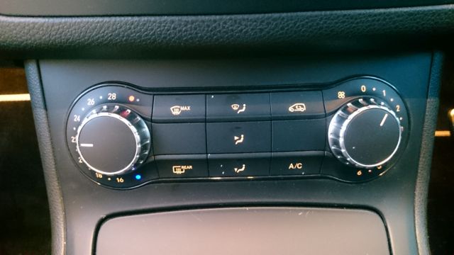
This air conditioning panel for instance is from a late 'B' Class and as you can see has the dots between the numbers on the blower dial, I would therefore conclude that the same facility is available on the late 'B' Class as is available on Warwick's A170 2007 model.
Please Note
I have now researched this matter further and my W169 A150 2009 model is fitted with a different regulator Part number :-MB 169 820 03 97 So I stress if you have blower regulator problems then order your spare part using you OWN vehicle Vin Number, or you may find that all your work in replacing the regulator was in vain in that the Blower motor will still not operate. I am still of the opinion that the regulator provided would be removed/fitted in the same location although connections going to the regulator may be different to those shown on this page.
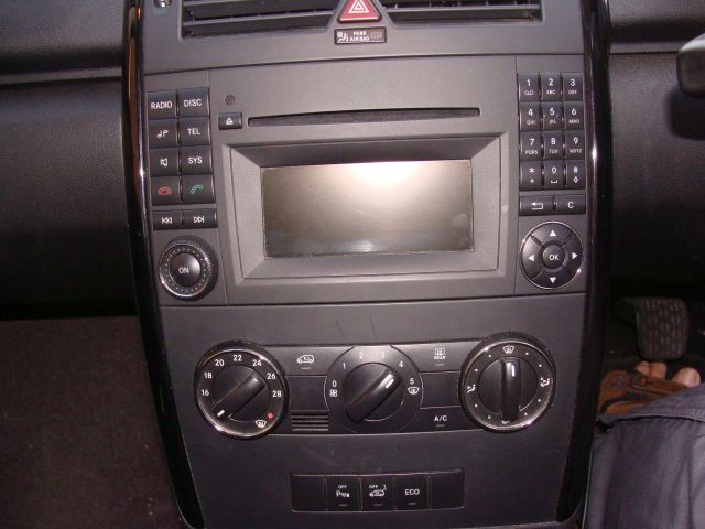
What we do know is that the 2009/W169 has different controls, these are the controls in my own W169 A150 2009 Classic model.
What we do now know is that Warwick's Blower regulator/control is totally different to the W168 which is a basic resister relatively cheap to replace and easy to fit. But in keeping with almost everything MB do on their vehicles the W169 regulator appears to be over sophisticated for the job it does and as a result costs considerably more (over £100) as well as being very difficult to get at and replace. A Mercedes_Benz ploy to stop you locating and fitting a new regulator DIY I suspect.
Note
Those of you that use my pages for repairs on your vehicles will be aware that when ever dealing with electrical components I disconnect the battery, Although it may not be considered necessary in this case ensure the ignition keys are withdrawn from the ignition and do not replace until the all cables and components are fitted, ie job is complete.
This information has been provided by Warwick enhanced with some detail from Lofty .
Note.
The procedure for replacing the Regulator is set out below.
1.The W169 model A170/2007 in this article is equipped with an electronic controller (regulator) rather than a resistor bank, as used in the W168 models. If the control switch for the blower has only five or six positions, the use of a resistor bank affords simple control. However, should you find that you have twelve stop positions as on my switch it is highly likely that you are dealing with an electronic controller. But since the electronic controller allows for greater energy efficiency, you could still have an electronic unit if you car is a later model that still have five or six positions for its control switch.
2. If the blower will not operate, first check the fuse. If a fuse has blown, it is likely that a replacement will also blow, indicating the presence of a short circuit, so the fault/cause must be traced before installing even new fuses. If however the fuse is intact, it is likely that the blower regulator is at fault.
3. Access to the controller/regulator is more difficult than in earlier models, but if you follow the method outlined here it is a manageable DIY task.
4. First move the driver’s seat (right Hand Drive) Passenger seat in left hand drive) back as far as it will go which will allow you more space to work.
5. You now need to remove the plastic panel which is located above the drivers knees. (right Hand drive) You will require a T20 Torx bit and a medium size Phillips screw driver
6. Pull the bonnet release, red lever fully down, the bonnet will release. Under the lever you will locate a Phillips screw, fully undo and remove the screw, this will release the lever and bracket. I have shown the screw to assist in its location.
7. There is no need to remove the diagnostics housing screws providing you are familiar with the securing clip on the rear of the panel as once this is removed the contact block will be released from the housing and can passed through the plastic under tray. However DO Not Pull on the wires or twist the wires while releasing the clip.
8. Remove the two Torx from the plastic under tray and ease down.
9. Feed the bonnet release lever and bracket through the opening in the panel thereby releasing it, position out of the way.
10. Move/Position the plastic tray in such a way as to be able to get at the back of the panel.
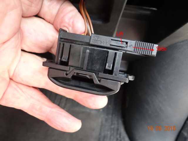
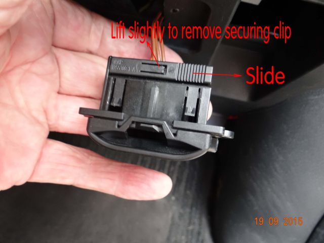
11. You now need to release the diagnostics contact block, (a) Take and hold the grip section of the plug, pull right, out and away from the housing .
b). Using two pins, lift and secure the two rectangular plastic clips situated either side of the clip. When both side are lifted and held away from the housing, slide the clip off of the housing remove the pins to release the clips.( Take care not to damage the rectangular clips )
Note that the wires going to the diagnostics plug are in the main brown, the chances of replacing these correctly if pulled from the connection block is remote so take care.
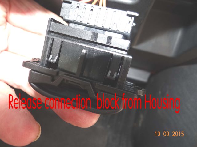
(c) Now ease the wired contact block away from it's housing. The plug can now be placed through the hole in the plastic under tray. I released the Diagnostics Housing by removing the two Torx screws this enabled me to lower and turn the plastic under tray without twisting the cables going to the diagnostics contact block. It also made it easier to photograph.
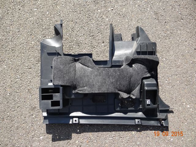
12. The under tray can now be moved to a safe place along with the screws and diagnostics block housing if removed.
There will be some wires and small hose that cannot be moved , take car not the apply pressure on these while working.
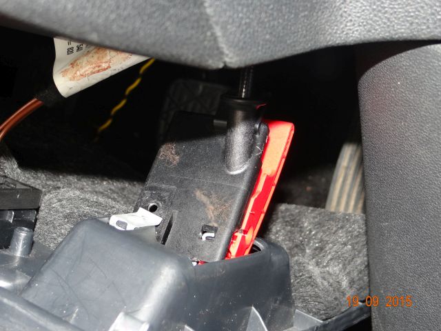
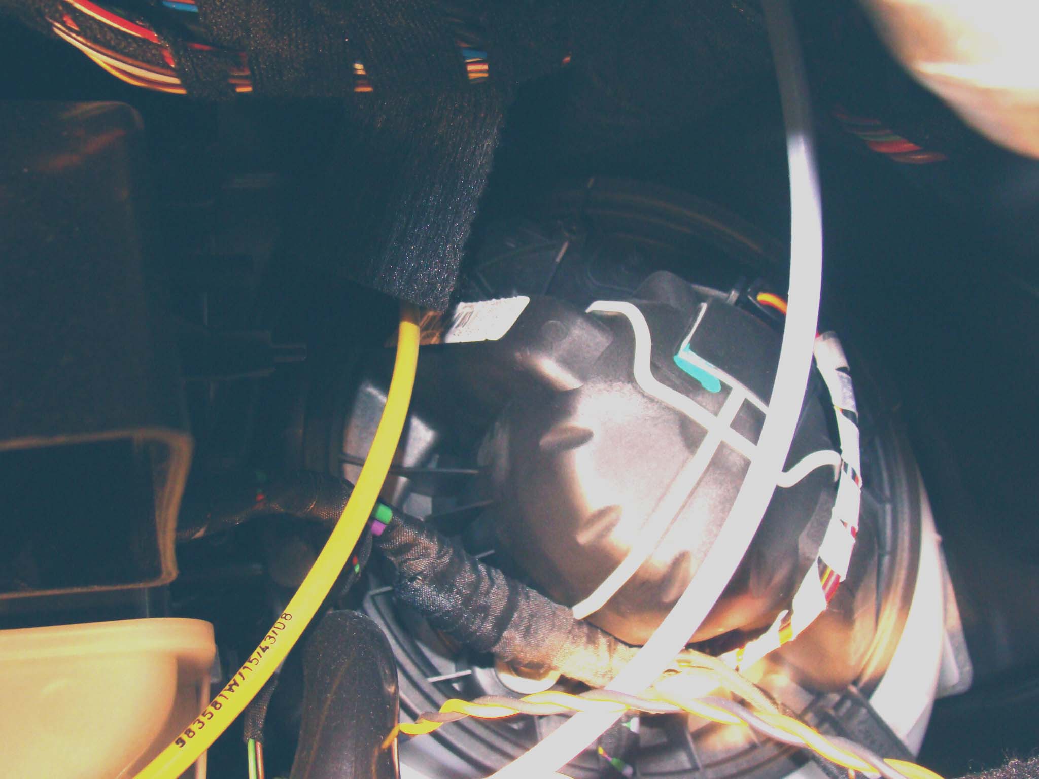
13. Position yourself so as to be able to look up and under the dash area, If you look you will see the black plastic heater housing which has white stripes as shown in the accompanying picture.
The regulator is located in the area of the red Box.
The Yellow and Black cable cannot be disconnected so ensure you do not apply pressure on the cable or contact either end may be lost
This photo shows what you can see at the start of the job and what it should look like when you have finished! The two Torx screws to be removed to release the regulator are the shiny silver ones toward the top of the picture, there are also two screws shown lower down they have nothing to do with the regulator.
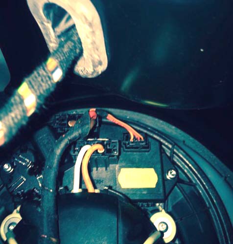
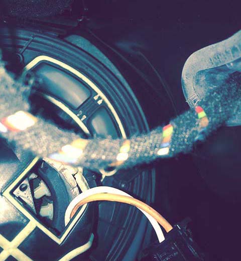
These two photos shows:- (a). The clip-on cover over the smaller of the two holes in the blower housing, through which the blower motor wires run.
(b). The two wires fit in small grooves in the upper edge of that opening.
(c). The four small control wires and the plug still in place in the regulator body.
(d). The two heavy wires into the regulator are just obscured beneath the wiring loom.
14. Removal of the regulator is effected by removing the two Torx screws either side of the regulator and lifting it out of its position in the blower housing.
Having removed the regulator release the locking tabs and release the three plugs connected into the regulator. Should you have unusual dexterity, you may be able to unplug the cables before removing the regulator, but it is easier to perform this task when the regulator is out of the blower housing take care not to pull on the cables/loom.
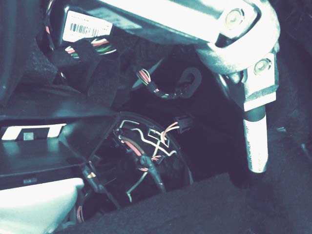
This photo shows more clearly the location of the Blower regulator which is 120mm x 50mm x 60mm The UJ is part of the steering column
15. Replacing the unit is easier, replace the components in reverse order.
Warwick's Observations As an Electrical Engineer.
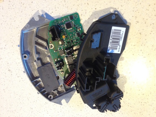
In Australia, where operating conditions are hotter than in Europe, I have some reservations about the design of this regulator. The unit comes with a substantial die cast aluminium heat sink on to which the electronic components are fixed. The devices on the printed circuit board that switch the current to the motor are those which develop most of the heat for disposal by the heat sink but the heat sink is mounted on the opposite side of the circuit board to the switching devices needing heat relief. So thermal contact with the heat sink is only effected after the heat has flowed through the circuit board and the thermally conductive tape situated between the board and the heat sink.
I would guess that in manufacture the tape was well dressed with a thermally conductive paste to aid the heat transfer process but in my unit, if there was ever paste it had dried out completely.
The result of this when operating in the hot Australian environment is that the switching devices burned out.
However Mercedes had partially anticipated the problem of the need to remove the heat created in that they installed the regulator in the blower air stream but in doing so made replacement/servicing of the regulator very difficult.
It is hoped that this information will be of help to owners who suffer heater/blower problems.
Warwick Nichols
Even if you are unable or just not prepared to tackle this job it will give you some idea of the work involved, degree of difficulty and why the cost of replacing this component is so high made up of course by the cost of the replacement regulator £??.?? labour costs and the dreaded 20% vat on both.
If you did disconnect your battery remember to use the correct sequence for refitting the terminals.
1. Turn main light switch to at least side lights, this action prevents a serge of power hitting the ECU which is likely to cause the Engine management light to come on when the engine is started for the first time after the repair. The only was this light can be deleted is by using diagnostics tools to clear the fault from the ECU.
2. Disconnect the negative terminal followed by the positive
3. When replacing fit the positive terminal first followed by the negative
4. Turn off lights.
5. Having completed, test and record your repair.
Follow up to replacement of regulator.
Well I had an e-mail from Warwick in Australia today 23/10/15 and the new regulator he installed 4 weeks ago has failed, he is obviously expecting the company to replace it FOC but that does not compensate for the inconvenience and work needed to replace it again.
If you have suffered problems with your heater blower regulator please let me know so that we can come up with some alternative to spending hundreds of ££££ on blower regulators.
I received this information from Roddy and I sure that other owners with a little DIY could copy his procedure for repairing the Blower Resistor. This information also confirms that some W169s are fitted with resistors and not a regulators like Warwick's in Australia.
Thank you Rod for your input.
Hi Lofty,
Just want to add a bit regarding Blower Resistor problems.
I had exactly the same problem on my 2006 A Class, only working on the Max setting.
After extracting the resistor module I decided to check the component attached to the end of the module, which is a 240 degrees centigrade thermal fuse, which when tested with a multi meter was found to be open circuit.
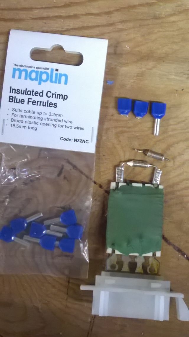
I sourced a new component from Maplins for £0.99p (code RA23) and some crimps to attach it (CODE N32NC), £1.69 a pack. I don't think you can solder this component, I suspect due to the high temperatures it experiences.
I carefully snipped the old component off, taking care not to damage the lugs, and attached the new one by utilising only the metal portion of the electrical crimps and attaching the thermal fuse to the resistor pack lugs by crimping with a pair of snipe nose pliers and wire cutters.
Blower is now operating fine.
I found used resistor packs available on e-bay UK for around £25.00, but from what I can gather, this thermal fuse seems to be the common fault with these blower resistors.
Hi Lofty,
The Resistor pack was located at the rear of the central panel blower housing and quite accessible, a lot easier than your own earlier model by the sounds of it.
Remove the plastic under panel as with the procedure above.
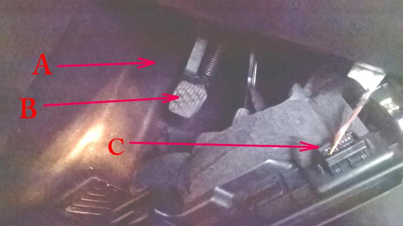
The panel can be totally removed if the Diagnostics plug is released. If you do note totally remove it from the car make sure you do not apply tension on the cables going to the Diagnostics plug. You will now have access to the carpet edge behind the clutch pedal Taking car, the carpet can be pulled beck and away from the trim edge of the centre consul just to the left of the clutch pedal The resistor pack on my car could then be clearly seen and quite easily accessed. A Location of resistor pack and housing
B Clutch (Manual transmission).
C Under panel supported showing underside of diagnostics plug and loom.
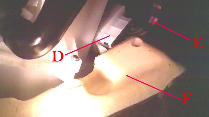
D Resistor in its housed location E electrical loom going to resistor
F Heavy foam backing on underside of carpet.
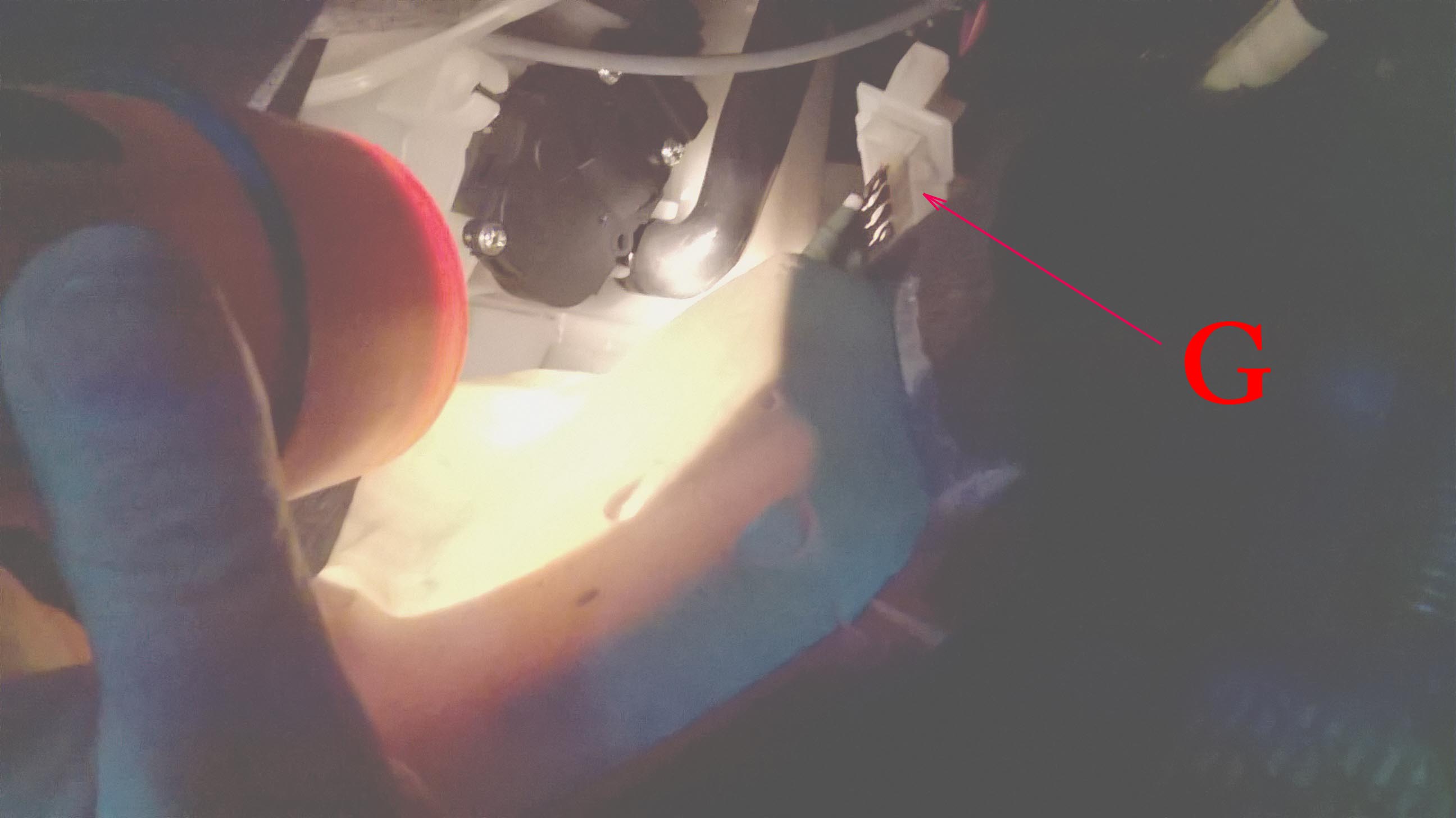
G shows resistor removed from Housing.
1. You need to remove the plastic panel from under the steering wheel and directly above the pedals. It is held on with 2 Torx screws and comes off fairly easily, best if you start prising from the left side first, there is a clip mechanism on the right side. This panel will then dangle on the cable of the Diagnostics test socket and the bonnet opening mechanism.
2. You need to carefully pull back the carpet starting from behind the clutch pedal and prise it from under the trim of the central consul, enough to allow you to access the area behind and to the left of the clutch pedal. This took a bit of effort and care not to damage the trim.
3. You can then see and access the Resistor pack, which is to the rear of the blower unit housing.
4. Taking your time, you can remove, repair and re-fit comfortably within an hour.
Best wishes
Roddy
What is still in question is what W169's have regulators like Warwick's above and what year and models is the resistor fitted to, Certainly before buying either unit you need to check with Mercedes parts what your individual car is fitted with you do need to provide your Vehicle Vin number to get the correct information.
This e-mail has been received from Fergus who has added some detail that he hopes will help other owners when removing the defective parts from the blower assembly.
Hi Lofty,
As a previous buyer of your DVD, thank you for keeping this information in an accessible place.
My dad has a W169 with the Automatic climate control (12 speed settings) and in late 2015 the blower stopped working, I looked at the filter and found it to be soaked with water and a great pool of water was just lapping at the bottom edge of the filter.. I used my wet/dry vac to clean out the debris (lots of leaves and soil, presumable from dirt/dust and broken down leaves), made sure that water was able to drain away and then replaced the filter with a new aftermarket one.
Being a right hand drive vehicle, I used your site to take off the panel under the steering wheel and turned the blower to full, nothing happened, a tap with a rubber mallet brought the thing to life.. I thought this meant the brushes were going, the blower continued to work for approx 6 months, this time, no amount of hitting it would get it running.
I removed the electronic control module with a T20 torx bit, whihc is the same part as Warrick's and then it was time to remove the blower, there's not much info on doing this... other than a poor chap exclaiming that he had removed it but could not get it out past the steering column and carpet...
To remove the blower, there's a tab on the lower left side of it (closest side to inside the car), this had a hole for a screw but no screw installed. On the opposite side of the blower, closest the firewall, you can see another straight tab, this one locked hard up against a sloping plastic locking tab on the white heater core surround. To remove, lift that tab out towards you, clear the edge of the white tab and rotate the whole blower assembly clock-wise. It will loosen and then you can pull the blower out and fun begins..
I did this the hard way, by gently prying it out past the steering column and heater foot vent and wiring loom (I had to gently tuck the loom out of the way and where necessary push the big look up a little to allow me to rotate/squeeze/bend the blower assembly out of the space, in short, it was difficult.
Having removed it, I could see an easier way.., As I had already removed the electronic control module, there's 3 screws left which simply hold the black round plastic motor housing to the motor hub, remove these with a T15 torx bit, pry the little rectangular plastic wire cover up at the edge closest to the brown and white wires and remove it then you can quite easily remove the plastic housing out of the way and then gently angle the motor hub thru the gap between the steering column, foot duct and carpet to remove it, yes it scrapes past but it's not harmful.
I ordered a replacement Valeo unit, with my VIN#, this came with a brand new electronic control module already installed.
I disassembled this in the same manner, taking care to note the gap/recess in the plastic housing for the motor wiring and then Installation was difficult but manageable and is the reverse of the procedure I described above, the hardest part being to mate the black plastic housing back onto to the motor hub, as there is very limited room.
All up it took about 45mins to remove and similar time to re-install the new unit.
I've take some pictures, which might be helpful and can send them through if you wish to add this information to your site. (It is hoped that these can be added later Lofty)
Kind Regards,
Fergus Reaper

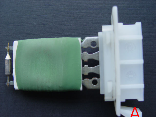 I had assumed that the resistor, Photo 'A' as fitted to the W168 would be the same on the W169 (This has since proved to be the case because Roddy's car was fitted with the same resistor as the w169, his car is a 2006 W169) and as the heater controls and display was much the same on the European version and advised him accordingly, however after much searching both here and Australia it was concluded that the location of the blower resistor must have changed, but where was it?
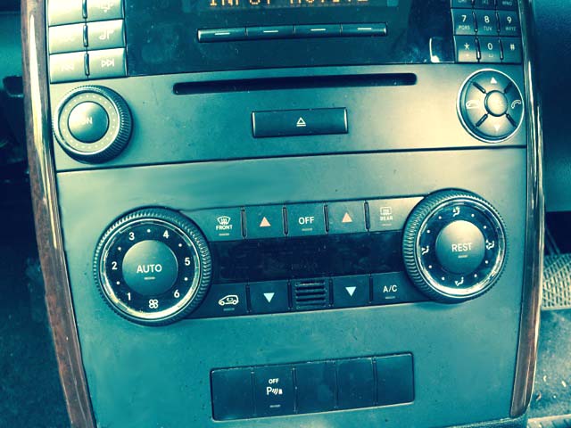
 What we do now know is that Warwick's Blower regulator/control is totally different to the W168 which is a basic resister relatively cheap to replace and easy to fit.
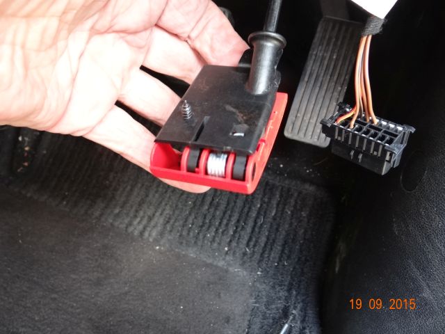
 6. Pull the bonnet release, red lever fully down, the bonnet will release. Under the lever you will locate a Phillips screw, fully undo and remove the screw, this will release the lever and bracket.
 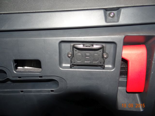 7. There is no need to remove the diagnostics housing screws providing you are familiar with the securing clip on the rear of the panel as once this is removed the contact block will be released from the housing and can passed through the plastic under tray. However DO Not Pull on the wires or twist the wires while releasing the clip.
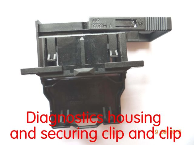
 13. Position yourself so as to be able to look up and under the dash area, If you look you will see the black plastic heater housing which has white stripes as shown in the accompanying picture.
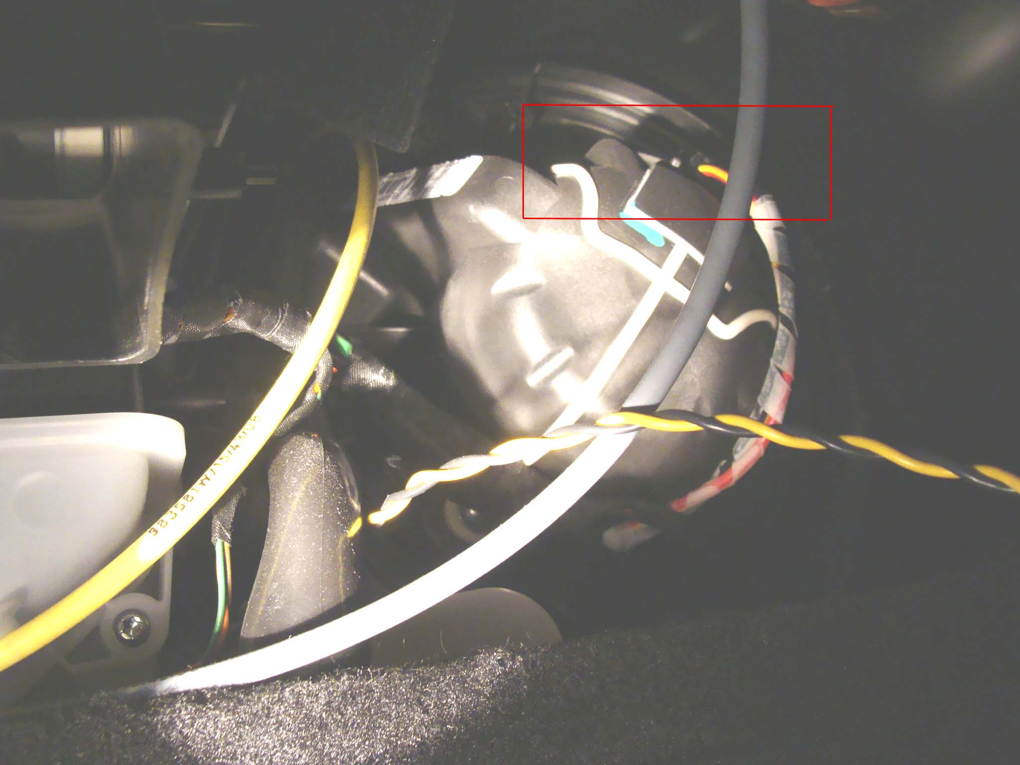
 Hi Lofty,