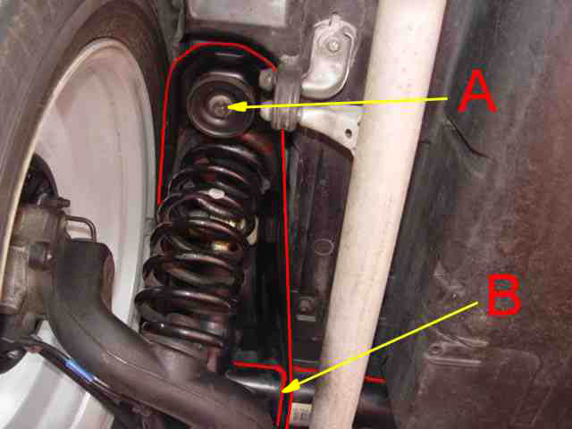
The rear suspension consists of a sub-frame Part number 16835 05700 1 199 0255 04 Mounted and bolted onto the underside of the body work, Chassis, almost certainly rubber mounting pads are positioned between the sub-frame and the bodywork the rears being mounted in the metal housing of the sub-frame A There are two mountings at the front and two at the rear, although the fronts are not so easy to find. I have outlined the sub-frame where it can be seen, The large oval cross member B forms the mechanical link between the N/S & O/S wings forming a large ridged 'U' shaped frame on which the other suspension components, swinging arms and rear wheel hubs are mounted.
The mountings and securing bolts are displayed in these photographs , the fronts are difficult to see and suspect even more difficult to get at and work on should it become necessary.
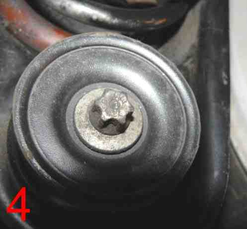
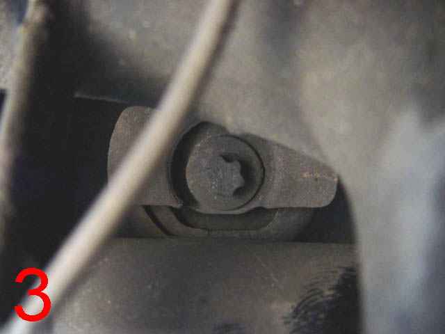
3 Fronts 4 Rears
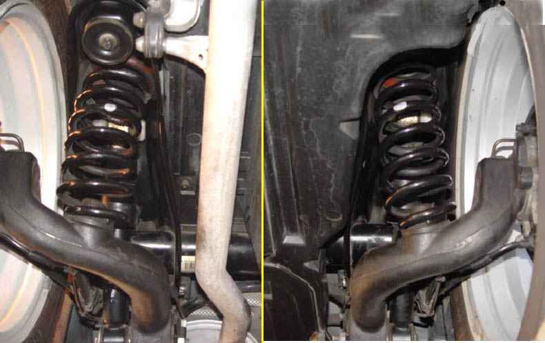
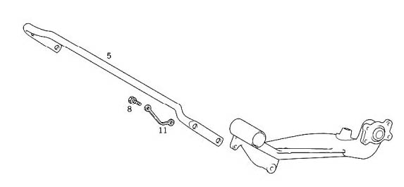
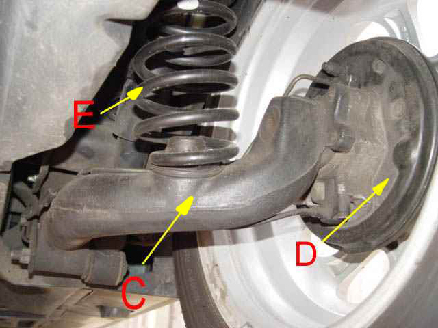 Situated between the static wing of the sub-frame and the movable swinging arm is the coil spring which makes up the rear suspension
 It should be noted that the spring lays at a slight angle in relation to the rear of the car, as weight is applied so the springs straighten the load being applied directly over the swinging arm.
C Swinging Arm
D Rear Wheel Hub Assembly
E Rear Suspension Coil Spring.
 1
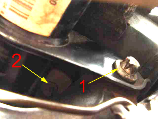
The trailing arm securing bolt.
1
The trailing arm securing bolt. 2 One of the front sub frame securing bolt.
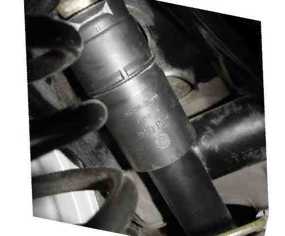
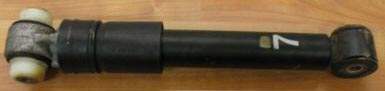
Shock absorber marked with a part number. E4SR4 Z007A00 The top of the shock absorber is bolted to the wings of the sub-frame and the bottom to the swinging arms Their function is as their name implies to reduce shock through the chassis & body of the vehicle when travelling over rough terrain, thereby reducing erratic spring movement of the vehicle, which in turn stabilizes the movement of the car. Defective units will show themselves in the that they invariably leak the hydraulic fluid contained within them and then allow a lot of bounce on the corner where the defective unit is located. When replacing shock absorbers, unless a new unit fails it is normal to replace both units i.e. fronts or rears. This of course does depend on the age of the units but the front or rear of the car need to remain balanced, shock absorbers do after a period of use become less effective than when new, hence the reason to fit replacements in pairs.
 Both top and bottom
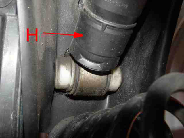
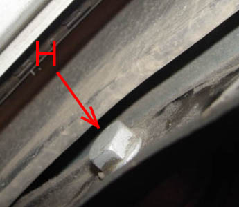
H and 5 shock absorbers are secured by bolts, The ones at the bottom are easier to get at than the top but both can be reached with ring spanners. Access to the outer shock and trailing arm bolts Both top and bottom
6
is via the wheel arch by removing the wheel arch liner.
Both top and bottom
H and 5 shock absorbers are secured by bolts, The ones at the bottom are easier to get at than the top but both can be reached with ring spanners. Access to the outer shock and trailing arm bolts Both top and bottom
6
is via the wheel arch by removing the wheel arch liner. 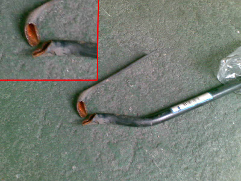
 Also Secured by the same fixing is the end of the Rear Torsion bar, one being located either side. This unit was removed from Sergio's car it having done approx 50,000 miles, as can be seen the bar it is not only hollow but has sheared through, judging from the metal the break has been hanging on by a very small amount for some time however unlike the front springs this was heard to finally break by the owner who has obviously replaced it.
His comments like mine are not very complimentary about Mercedes-Benz for fitting a hollow torsion bar, something neither of us have ever heard of before.
A contradiction of terms because these bars are normally solid sprung steel, this component is nothing other than a piece of hollow tube and it is difficult to see where the term torsion is applied to this unit, the continuous twisting or torque of this unit must cause fatigue and after time failure. I can only think that in the case of the 'A' Class this component does little work or we would I'm sure have heard of more defects of this nature and this in my experience is the first to come to my attention.
Never the less when checking your car for M.O.T (Ministry Of Transport Test )or if you have rear suspension problems, including unusual rear tyre wear, Check the rear torsion units (bars).
Having said that Sergio reminds me that things aren't quite as simple as just checking because the plastic under floor pans at the rear of the car have to lowered to see and get at the fixings fully, owners will be aware that that is not easy due to the pans being hinged on the n/side and therefore the vehicle has to be elevated to a reasonable height before the pans will drop low enough to be able to inspect and get at the fixings etc.
Remember always work safe
Remember when checking shock absorbers apart from looking for leaking, the bushes need to be in a sound serviceable condition.
This information received from an owner may help those of you who cannot locate or get a spanner onto the top shock-absorber outer bolt head.
Hi Lofty,
Have owned our A170 for a few years and have used your FAQ a few times - many thanks.
Read you advise on changing rear shockers - the top bolt is completely hidden between sub-frame and chassis.
I've just replaced mine and found the easiest way was to undo the two rear sub-frame bolts and lower the rear sub-frame on a jack until it exposes the top shocker bolts (with the rear of the car on axle stands). Hope this can be of some help
Thanks(Although i managed to photograph the one on my car it isn't easy to get at, the inner wing lining is semi flexible, I was able to locate an open ended spanner on it, but you may need two pairs of hands to undo the bolt and keep the spanner located. (In the case of older cars, where sub frame bolts show signs of rust, lubricate prior to attempting to slacken/remove, take great care not to shear these off)
You may well find that useful but take great care to ensure the car is stable whilst you work, axle stands or blocks are essential, never rely on jack's alone.
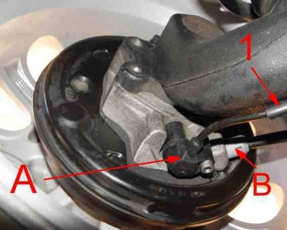
Not technically part of the suspension but while we are here we might as well look at the components on the back plate of the hub, on the lower edge of the back plate we can see the sensor for the ESP/ABS systems A which obviously pick up there readings from the stub axle. Also the handbrake cable connection. . B
One word I noticed that the outer casing of the of the wire carrier for the ESP was wearing against the swinging arm and so placed another rubber buffer 1 around the casing effectively moving it away from the rough casting of the swinging arm.
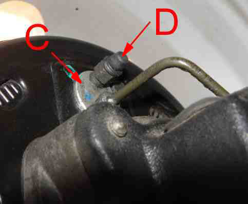
On the top edge, the body of the wheel cylinder can be seen C along with the bleed valve assembly, worth checking to see the bleed valve protective cover is in place. . D
Next.
Back to Index,
Purchase DVD.
Please Make a Donation.