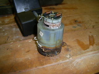
 Here's one sorry looking pump.
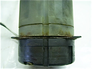 Note the line up of the rounded groove all the way down the nylon
and ceramic body.
Note the line up of the rounded groove all the way down the nylon
and ceramic body.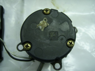 Remove the three screws from the bottom end.
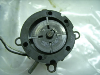 Note the four rectangular "slides", these move outwards due to
centrifugal force to create the suck and blow. The second outer ring
comes off. Remove the four slides ... don't lose them.
Note the four rectangular "slides", these move outwards due to
centrifugal force to create the suck and blow. The second outer ring
comes off. Remove the four slides ... don't lose them.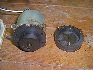 I was then stuck as to how the rest came apart but as you can see
the top "key" appears to be an interference fit on the semi-circular
spindle end and I managed to gently lever it off by carefully
inserting feeler gauges between the rotor and the back plate, then
gentle persuasion with a couple of screwdrivers helped to ease off
the top. The rotor then pulls off the spindle.
I was then stuck as to how the rest came apart but as you can see
the top "key" appears to be an interference fit on the semi-circular
spindle end and I managed to gently lever it off by carefully
inserting feeler gauges between the rotor and the back plate, then
gentle persuasion with a couple of screwdrivers helped to ease off
the top. The rotor then pulls off the spindle.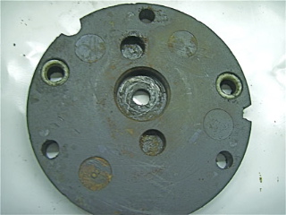 This is the reverse of the last ceramic back plate. You may find it
has sealant to glue it to the metal plate. Note the two "o" rings
These seal the nylon inlet/outlet tubes on the nylon body. Place
them into the back plate as it will be easier to fit later. The
middle recess holds the bearing.
This is the reverse of the last ceramic back plate. You may find it
has sealant to glue it to the metal plate. Note the two "o" rings
These seal the nylon inlet/outlet tubes on the nylon body. Place
them into the back plate as it will be easier to fit later. The
middle recess holds the bearing.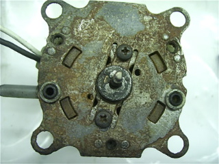 Note which way the bearing sits when removing it. Also see the two
"o" rings ... don't lose them. Remove the two screws that holds the
metal plate to the motor body.
Note which way the bearing sits when removing it. Also see the two
"o" rings ... don't lose them. Remove the two screws that holds the
metal plate to the motor body.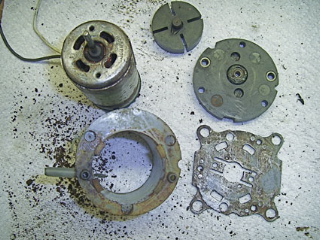 The metal plate may come away with the nylon outer casing, it may
also have sealant to hold the two together. I didn't do anything
with the top end of the motor (brushes etc)
from the bearing which fell into the motor body.
The metal plate may come away with the nylon outer casing, it may
also have sealant to hold the two together. I didn't do anything
with the top end of the motor (brushes etc)
from the bearing which fell into the motor body.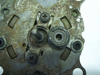 Here's my bearing .... well stuffed. I don't know if it was a sealed
lubricated unit or solid as this appeared. I basically cleaned all the
parts and re-assembled, the pump was not up to scratch
and overran, this caused overheating and smoke. I purchased a s/h
pump on E-bay and was fitted within minutes and all worked ok.
When re-fitting ensure that no sealant gets into the "o" ring holes
or the bearing. Make sure the bearing is the correct way round . Fit
the ceramic back plate with the "o" rings already in situ.
fit the rotor and top cap ... tap it gently in place. Fit the middle
ceramic ring .... make sure that the central groove is aligned as
Fit the four rectangular ceramic "slides" make sure they are the
correct way round ... they should match the rotor slots and not
checking that the body groove lines up. It may be prudent to remove
volt supply ... I used a battery charger. It doesn't matter which
way round the connections are made as it will either suck or blow. I
suggest carefully securing the screws with the motor running as you
can hear the motor labour if the ceramic body parts are not aligned
correctly.
Here's my bearing .... well stuffed. I don't know if it was a sealed
lubricated unit or solid as this appeared. I basically cleaned all the
parts and re-assembled, the pump was not up to scratch
and overran, this caused overheating and smoke. I purchased a s/h
pump on E-bay and was fitted within minutes and all worked ok.
When re-fitting ensure that no sealant gets into the "o" ring holes
or the bearing. Make sure the bearing is the correct way round . Fit
the ceramic back plate with the "o" rings already in situ.
fit the rotor and top cap ... tap it gently in place. Fit the middle
ceramic ring .... make sure that the central groove is aligned as
Fit the four rectangular ceramic "slides" make sure they are the
correct way round ... they should match the rotor slots and not
checking that the body groove lines up. It may be prudent to remove
volt supply ... I used a battery charger. It doesn't matter which
way round the connections are made as it will either suck or blow. I
suggest carefully securing the screws with the motor running as you
can hear the motor labour if the ceramic body parts are not aligned
correctly.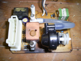 If you are interested here are a few pictures of the circuit board
and the connector.
If you are interested here are a few pictures of the circuit board
and the connector.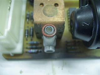 The top right hand corner component is like a clockwork motor and
seems to wind when moved/tapped.
The top right hand corner component is like a clockwork motor and
seems to wind when moved/tapped.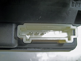 Note that there are three "o" rings which may stay in the black
plastic housing or come off with the circuit board.
Note that there are three "o" rings which may stay in the black
plastic housing or come off with the circuit board.